Firstly I would advise against using SOT23 devices, unless you know how to connect them to a common heat sink.
They have less heat dissipation capability than TO92 without heat sinks.
In that sense LSK389 is better in two ways :
a) it is automatically a matched pair -- assuming you use one JFET in each SOIC8 for the top & the other for the bottom;
b) the SOIC8 package can dissipate more heat than 2x SOT23, and easier to attach to a heat sink.
But if I were to do it using currently available devices and commercial heat sinks, I would probably use 3x LSK389B in parallel, each having its own heat sink.
A TO-18 heats sink should fit, but you should try fist.
Wakefield USA Transistor Heatsink to 18 to 72 28 40 44 Board Level Power X1 | eBay
Patrick
Patrick, is there anywhere else where i can get the sinks if you don't take orders any more??
can't you just bootleg some heatsink? I thought this was for thermal tracking and not dissipation purposes
> is there anywhere else where i can get the sinks if you don't take orders any more??
No.
> can't you just bootleg some heat sink?
Get a piece of Aluminium about 14mm x 7mm x 4mm.
Drill 2x 5mm holes close to each other.
Plug in the TO92's and fill the gap with silver epoxy.
Not as good as ours, but better than no thermal connection.
Can also use a suitable size DIP IC heat sink to replace the aluminium above.
Patrick
Conductive Polymer Tantalum Solid Capacitors (POSCAP) | Industrial Devices & Solutions | Panasonic
Why not? Any reason?
...will add footprints for OSCON´s...
Why not? Any reason?
...will add footprints for OSCON´s...
Have not used them before, so cannot comment.
I would have chosen something like these :
http://www.mouser.com/ds/2/293/e-un-27549.pdf
Patrick
I would have chosen something like these :
http://www.mouser.com/ds/2/293/e-un-27549.pdf
Patrick
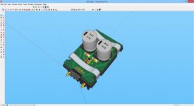
... with bipolars, caps I mean, and meanly COTS components (Mouser, Farnell, Digi-Key).
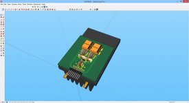
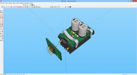
Last picture ist with DIP adapter (AD844)...
Jean-Paul
Last picture ist with DIP adapter (AD844)...
Jean-Paul

I hope you realise that you cannot just plug the SEN 1:1 into an existing circuit for AD844.
Among others, you will need one floating supply for EACH channel / phase.
AD844 can work with fixed rails (Gnd referenced), SEN cannot.
If you wish to use fixed rails, then you need to use something like Nelson Pass's ZEN IV.
Patrick
Among others, you will need one floating supply for EACH channel / phase.
AD844 can work with fixed rails (Gnd referenced), SEN cannot.
If you wish to use fixed rails, then you need to use something like Nelson Pass's ZEN IV.
Patrick
Hello Patrick,
I know that the supply needs to be floating. This will be a remark in the documentation. You can replace the AD844 but you must guarantee floating supply.
You don´t need to use the DIP8 adapter for this/your converter in new design, but it could be a very good replacement for existing designs.
I want to use this I/V converter in a design based on the DSC1 (last part missing is the JFET Sallen-Key filter: in doing, using SO8 LSK389).
I like your I/V converter, finally something that´s not directly from Mr. Pass. Like in music business, nothing really very exiting over the last years. I hate covered music.
Jean-Paul
Hello Patrick,
I´m refering to #1736.
I´ve read the Linear Audio vol. 2 article.
The 4x AVCT595 (5V supplied) + 32x 15k is a single rail DAC right (0,34 to 10,67mA), right?
Now my question, how can I achieve the high bias (24mA or more as you mentionned)?
Regards
Jean-Paul
I´m refering to #1736.
I´ve read the Linear Audio vol. 2 article.
The 4x AVCT595 (5V supplied) + 32x 15k is a single rail DAC right (0,34 to 10,67mA), right?
Now my question, how can I achieve the high bias (24mA or more as you mentionned)?
Regards
Jean-Paul
> The 4x AVCT595 (5V supplied) + 32x 15k is a single rail DAC right (0,34 to 10,67mA), right?
Yes, but this will only give you a unipolar output of 0V to +5.34V at thr 500R Riv.
This is also the case in your schematics uing AD844.
To achieve a bipolar output (+/-2.67V), you need to have a current sink before the SEN after the 595's of 5.34mA.
Or you put the gates of the JFETs at Vdd/2 (2.5V).
See the implementation for ES9018.
And you need to check whether the 595s can source AND sink current.
> how can I achieve the high bias (24mA or more as you mentioned)?
JFETs are elf biased at their Idss.
3x LK389B hould give you a total Idss of 18~36mA, which should be OK when you include the current sink mentioned above,
Patrick
- Home
- Source & Line
- Digital Line Level
- Zen -> Cen -> Sen, evolution of a minimalistic IV Converter