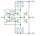
Since the merits of the floating supply keeps coming under scrutiny, I managed to dig out a circuit which I believe originates from Mr. Loesch.
It is basically the same folded cascode design as I posted here but with JFETs as cascode device instead of MOSFETs :
http://www.diyaudio.com/forums/pass-labs/173291-zen-i-v-converter.html#post2298531
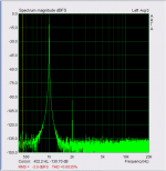
Using matched JFETs with 8mA Idss, floating 16V or +/-16V supplies, 2.4mA p-p sinusoidal current input at 1kHz,
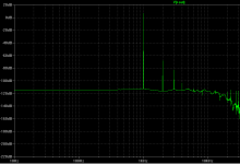
I used LT spice to simulate both circuits and compare the distortions.
As you can see in the middle figure, the folded cascode has some 15dB higher distortion, double the supply voltage and number of active devices.
So I guess the pain of the floating supply in the CEN / SEN is still well worth suffering.
Patrick
It is basically the same folded cascode design as I posted here but with JFETs as cascode device instead of MOSFETs :
http://www.diyaudio.com/forums/pass-labs/173291-zen-i-v-converter.html#post2298531
Using matched JFETs with 8mA Idss, floating 16V or +/-16V supplies, 2.4mA p-p sinusoidal current input at 1kHz,
I used LT spice to simulate both circuits and compare the distortions.
As you can see in the middle figure, the folded cascode has some 15dB higher distortion, double the supply voltage and number of active devices.
So I guess the pain of the floating supply in the CEN / SEN is still well worth suffering.
Patrick
Attachments

Have had it like that since i powered it up.Putting everything in an aluminium enclosure and earthing the case always helps.
Patrick
Patrick,
To avoid any misunderstanding, I don't blame the floating supply at all for my hum problems. I am sure I am responsible for whatever is causing it.
To avoid any misunderstanding, I don't blame the floating supply at all for my hum problems. I am sure I am responsible for whatever is causing it.
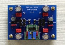
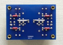
For those interested, here is our quick-&-dirty prototype of a SEN IV for PCM1794.
It uses the V2 PCBs, 8x 2SK369V per PCB (one balanced channel), and 2x 18V floating battery supplies per PCB.
Heat sinks not yet installed.
The P2P daughter board at the bottom is a dual 6.2mA Current drain using heavily degenerated 2SK369V.
The heavy degeneration to reduce 18mA Idss to 6.2mA is key to its low Vds(sat) and current stability.
The degeneration resistor also acts as current feedback.
The "tails" of the CCS are connected to an extra -9V battery (rel to DAC Gnd).
Listening test pending.
We still have some work to do to remove the original opamp IV to make space for the SEN.
😉
Patrick
Attachments
Since the merits of the floating supply keeps coming under scrutiny, I managed to dig out a circuit which I believe originates from Mr. Loesch.
It is basically the same folded cascode design as I posted here but with JFETs as cascode device instead of MOSFETs :
http://www.diyaudio.com/forums/pass-labs/173291-zen-i-v-converter.html#post2298531
Using matched JFETs with 8mA Idss, floating 16V or +/-16V supplies, 2.4mA p-p sinusoidal current input at 1kHz,
I used LT spice to simulate both circuits and compare the distortions.
As you can see in the middle figure, the folded cascode has some 15dB higher distortion, double the supply voltage and number of active devices.
So I guess the pain of the floating supply in the CEN / SEN is still well worth suffering.
Patrick
Patrick, one of my best sounding DAC based on pcm1794 is a folded cascode with k170/j74 very similar to your design, but I use current sources instead of R5 and R6.
The distortion measurement is from a similar design. The measurement was made with a pcm1794 at -3dbfs and only 2ºharmonic is measurable. This is a measurement of a real circuit , not a simulation. I real like the sound of this converter.
Attachments
I am sure measurement does not tell the whole story, and these simple JFET circuits almost always sound good.
We use something very similar in our XCEN Balanced to Single Ended converter.
http://www.diyaudio.com/forums/anal...ced-single-ended-converter-3.html#post3384411
We have listened to a few of these ourselves, but we always come back to the SEN / CEN with floating supply.
It is simply impossible to beat this (essentially) 2-JFET circuit.
But of course I am totally biased. 😉
Patrick
Since the merits of the floating supply keeps coming under scrutiny, I managed to dig out a circuit which I believe originates from Mr. Loesch...Patrick
Yes, that was my recollection when I first saw your post. Here is a link to the Thorsten circuit I believe you are thinking of. It's located midway down the page.
DIYHiFi.org • View topic - I/V convertor output buffer
Patrick, one of my best sounding DAC based on pcm1794 is a folded cascode...I real like the sound of this converter.
Sergio, I believe that you have created a significant number of interesting I/V circuits at this time. Can you say which of all those you feel sounds the very best with the PCM1794A?
Ken, I think that the biggest difference in sound quality is due to the layout of the PCB, and the power supply of the DAC chip.
Designing a I/V converter for this chip is very easy task, as the output impedance is very high, even a simple common base sounds very good, but the one that I personaly like the most is the folded cascode with input based on (2sk170/2sj74) and the output with darlington bjt, even a simple common source with 2sk170 sounds good. Jfets give a darker tone to this DAC.
with the es9018 I prefer, all bjt folded cascode.
So, despite never having heard the CEN or SEN, I am almost certain that they are a good I/V converter to use with PCM1794.
Floating current source
Patrick, one day I will try 🙂 , I promisse.
The problem is that I have a lot of ideas that I want to try, and to litle time.
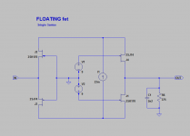
One idea that may interest you, is this one.
Using a floating current source, instead of a voltage source, with this circuit we have the benefits of the cascode with the possibility of not using capacitors at the output.
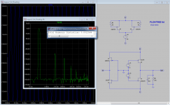
The simulated distortion of this is 0.001% with prevalence of even harmonics.
V1 and V2 are only to biasing the output jfet´s and will last for years without the need for maintenance.
If you like the idea, I would like to developed this with you.
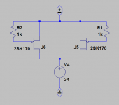
first image is the basic circuit, the second is one exemple of a floating current source.
Patrick, one day I will try 🙂 , I promisse.
The problem is that I have a lot of ideas that I want to try, and to litle time.
One idea that may interest you, is this one.
Using a floating current source, instead of a voltage source, with this circuit we have the benefits of the cascode with the possibility of not using capacitors at the output.
The simulated distortion of this is 0.001% with prevalence of even harmonics.
V1 and V2 are only to biasing the output jfet´s and will last for years without the need for maintenance.
If you like the idea, I would like to developed this with you.
first image is the basic circuit, the second is one exemple of a floating current source.
Attachments
Last edited:
Sergio,
VERY clever idea. Never thought of it that way. 🙂
Slight penalty though.
Now I need 2x9V battery, plus 1x 24V (or 27V), plus 4 more FETs.
And that compare to 2x9V, plus 2 resistors and 2 caps.
Perhaps we need to think a bit more to make it even simpler ?
Patrick
VERY clever idea. Never thought of it that way. 🙂
Slight penalty though.
Now I need 2x9V battery, plus 1x 24V (or 27V), plus 4 more FETs.
And that compare to 2x9V, plus 2 resistors and 2 caps.
Perhaps we need to think a bit more to make it even simpler ?
Patrick
I actually have an idea. Let's discuss offline.
(We learned our lessons and do not discuss development in public anymore as a matter of principle.)
I'll send you a email later once I checked my idea with simulation.
Cheers,
Patrick
(We learned our lessons and do not discuss development in public anymore as a matter of principle.)
I'll send you a email later once I checked my idea with simulation.
Cheers,
Patrick
I also prefer to develop offline, I have also my share of bad experiences when developing online.
It is possible to be simplified of course. One obvious simplification is the floating current source, that only
need one fet, two fets are not recommended, but I did not have the spice model of the fet that I want to use. V1 and V2 can also be discard.
🙂 glad you liked . Your experience in this type of circuits will be very important .
- Home
- Source & Line
- Digital Line Level
- Zen -> Cen -> Sen, evolution of a minimalistic IV Converter