Paul,
If your question is whether we shall have a poll here for what the public wants before we design, the answer is no.
I believe it art, and you cannot make art by democratic voting.
The first sentence I quoted in the F5X thread is that there are 100 ways to skin a cat.
I share with you my way, and you can decide whether you like it or not.
We are not here to win the popularity contest.
So as long as those who like our work really enjoy what we share, that is good enough.
And apparently, there are quite a few who do, and not just the F5X gang.
Having said that, where there are options that does not affect the sonic results, we are open for suggestions.
There have been many occasions like that in the F5X GB. Nic will testify to that.
We do not design to cost.
We don't intend to compete with Cambridge Audio for value for money.
We design to what we think is good audio engineering.
But at the same time, we are not known for blindly applying teflon caps, Black Gate NX, naked Vishays, ....., etc.
We think we choose our components sensibly.
Are they expensive ? Considering what you get, I don't think so. In fact, not all all.
But that is a judgement that other will have to make.
There are much cheaper ways to do DIY.
There are enough ebay dealers offering cheap PCBs.
One day, we expect some of our work will get copied.
So we concentrate on delivering a level of quality that makes ebayer not even bother to try.
Because top quality IS expensive, and bargain dealers won't want to spend the effort to achieve such quality levels.
This is our goal and our philosophy, as we have also explained in our website.
Patrick
Hi Patrick
That was most definitely not my question! My question was will your finalised ESS9018-SEN unit be available as a completed, assembly pcb subassembly- like Twisted Pear's Buffalo, or as a finalised, encased fully finalised unit for retail, or both? My question was prompted by your suggestion that some of those planning to build using the buffalo and SEN boards might want to wait for your finished product instead. I was just trying to clarify what they might expect from you, so they can best decide how to proceed.
For what it's worth I think the first buzz I reported is the result of rf pickup by the floating circuitry- which may be exciting some oscillation- and demodulation of af noise carried by the rf. Though I may ultimately fail to prove this due the limitations of my test equipment. The solution to this sort of problem- in my experience- is appropriate grounding and shielding (as you say), good layout, and the use of appropriate stoppers resistors and, sometimes, ferrites. Even measuring the circuit can affect its state of tune however, and cures tend to be whatever works in practice (like my- ungrounded- copper foil) to ensure rock like stability.
I was not implying that your circuit is intrinsically prone to oscillation or pickup. I suspect I could build my unit with a slighly different layout many times over and not experience any problems- I just got unlucky
Hope that's clear, and hopefully, uncontroversial 🙂
Best wishes
Paul N
I have to say that I admire the first quote, but think that if you were staying true to the philosophy you would be offering a DAC board/kit that the I/V was originally designed around (at least first.) Any chance of that ?
Yes, there will be a PCM1704 solution for our own use.
It is actually working, but we want to implement further optimisation.
But can you still get them ? And for how much longer ?
Patrick
It is actually working, but we want to implement further optimisation.
But can you still get them ? And for how much longer ?
Patrick
I admire your respect for intellectual properties.
But you already bought a hard copy, so you already paid Jan.
On top of that it is an arrangement between me and Jan to make the article available online after 6 months.
So you do not have to feel guilty about it.
You can make the PCM1794 to work with an additional current drain, I think.
That means e.g. an extra battery, a TL431, a NPN and a resistor.
I do not think you will have a thermal stability issue.
The TL431 has a tempco of 50ppm/°C, and you can also use a low tempco resistor.
I do not consider this 4-component circuit to be complicated ?
Please refer to post #784, or Fig.13, 14 of the Fairchild datasheet :
http://www.fairchildsemi.com/ds/TL/TL431A.pdf
Patrick
I received the magazine and read most of your article. Thanks for your hard work.
As for the PCM1794a and it's DC current offset, I don't trust a current drain for several reasons. One thing I did try in simulation was to merely put a capacitor between the current source and the input to the I/V converter and it works fine. What I don't understand about this though is why this capacitor doesn't effect the frequency response for the circuit. It seems to be just fine regardless of the capacitance. weird.
Also, one problem I see with something like this type of I/V circuit is that there's no common mode rejection from the DAC. I have read in a couple of different places that DAC's often have a significant common mode signal on their Iout+ and Iout- pins. I have not been able to track down exactly how significant is this signal though. The usual I/V converters, as shown in the datasheets for example, have an opamp performing the balanced to single ended conversion. Presumably the opamp has good CMRR. It would be better to have the high CMRR device directly connected to the DAC pins however. This is where I'm at right now. How do you get screaming high CMRR with virtually zero input impedance?
If you only take the positive phase out of the DAC and use it for your single ended audio chain, then it is true that you do not make use of the even harmonic cancellation of the balanced DAC itself, or whatever else common mode distortion that you might have.
Which is why it is, at least theoretically, better to use a Balanced to Single Ended converter, such as
http://www.diyaudio.com/forums/analog-line-level/216557-xcen-balanced-single-ended-converter.html
which performs the cancellation.
You can then philosophise whether the converter creates more even harmonic distortion at some -90dB, or one phase of the DAC itself.
Many DAC's only quote performance in differential mode. So you'll have to measure to find out, I guess.
Patrick
Last edited:
Thanks for your reply. I can't measure very well myself. I can't afford an Audio Precision analyzer (or anything equivalent to one). I have a computer based analyzer that's good to better than 100dB though (I think 110 dB at 1kHz at least) but the bandwidth is only 22kHz.
I'm still trying to figure out what kind of common mode signal is produced by the Iout- and Iout+ pins of this DAC. It's not in the data sheet as far as I can see.
The problem with doing the balanced to single ended conversion after the I/V conversion is that any common mode signal present will go through the I/V conversion and produce it's own spectrum of artifacts before the common mode signal is canceled in the differential amplifier stage. These artifacts will pass right through the differential stage because they are no longer common mode signals. In theory at least to me it seems that the ideal would be to have something connected directly to the Iout pins that had a high CMRR. More to think about. Thanks.
That is precisely the point of CEN / SEN.
Kirchoff's law ensures that the intrinsic distortion of the IV is so low that it does not really matter.
We can worry about all these theoretical considerations.
If you believe in numbers then just use an opamp IV.
The thing takes you half an hour to build. My first was on a breadboard.
And then just enjoy the music. If you don't like it then just take it apart.
It is much more productive then speculative discussions.
Cheers,
Patrick
I prefer to hammer out the details as much as possible before actually building something. I enjoy theoretical discussions also. Finally, I enjoy the creative process as well. It's just my personal preference.
I think I have something that I like very much now. Thanks for your inspiration, and thank you Dr. Leach, where ever you are now.
I think I have something that I like very much now. Thanks for your inspiration, and thank you Dr. Leach, where ever you are now.
Finished?
I think I might finally be done.
I have built a version of the last Sen variant I posted with RM=2.2MEG (the largest resistors I have) and Riv=910R using the most recent servo I posted with one extra decoupling capacitor on each servo and 3 150pF Civs per balanced channel. I used 6 pairs of JFETS per balanced half plus the extra pair of drivers to drive the gates to avoid the distortion increasing with frequency.
The last Sen variant I posted has much wider bandwidth than Sen owing to the extra pair of driver jfets and needs at least 1 Civ per balanced pair to reduce the bandwidth and eliminate radio frequency noise.
Initial listening test is very promising - retaining the clarity of my first successful Sen variant and a little less liquid at the high end - maybe a bit subtler.
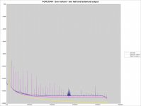
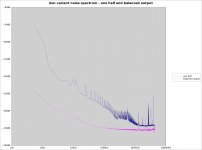
Here are the measured results including comparisons between one half and balanced output which someone requested:
Analyzing "sen-variant-final.flac"...
Frequency: 999.927046 Hz
THD+N: 0.0019% or -94.5 dB
Big thanks to Patrick for posting this thread.
I think I might finally be done.
I have built a version of the last Sen variant I posted with RM=2.2MEG (the largest resistors I have) and Riv=910R using the most recent servo I posted with one extra decoupling capacitor on each servo and 3 150pF Civs per balanced channel. I used 6 pairs of JFETS per balanced half plus the extra pair of drivers to drive the gates to avoid the distortion increasing with frequency.
The last Sen variant I posted has much wider bandwidth than Sen owing to the extra pair of driver jfets and needs at least 1 Civ per balanced pair to reduce the bandwidth and eliminate radio frequency noise.
Initial listening test is very promising - retaining the clarity of my first successful Sen variant and a little less liquid at the high end - maybe a bit subtler.
Here are the measured results including comparisons between one half and balanced output which someone requested:
Analyzing "sen-variant-final.flac"...
Frequency: 999.927046 Hz
THD+N: 0.0019% or -94.5 dB
Big thanks to Patrick for posting this thread.
Attachments

Last edited:
However, we live in EMI jungle. The floating power supply is an RF antenna, and through parasitic capacitances the RF it receives gets fed into the circuit.
You probably know better than I that an ungrounded shield is practically always worse than no shield at all. Your floating power supply is like an ungrounded shield.
Maybe in the final overall shielded I -> V converter it is not a real issue. But one should not blindly adopt floating supplies - everything has its price.
...
OK, so how would you make sure that RFI did not enter the required floating supply? Would small value ceramic capacitors connected between both the + and - sides of the floating supply and ground be sufficient?
OK, so how would you make sure that RFI did not enter the required floating supply? Would small value ceramic capacitors connected between both the + and - sides of the floating supply and ground be sufficient?
This will cause distortion because the current from the DAC will go to ground through the capacitors rather than Riv.
This will cause distortion because the current from the DAC will go to ground through the capacitors rather than Riv.
OK then what is your solution?
As mentioned in the article, R_iv and C_iv forms a 1st order low pass filter.
R_iv determines the output voltage level, or current to voltage conversion gain.
You can choose whatever values to suit your own application / liking.
Patrick
R_iv determines the output voltage level, or current to voltage conversion gain.
You can choose whatever values to suit your own application / liking.
Patrick
Hi
This was in the original SEN application which used a 2k7 IV resistor (appropriate for the DAC used), to give -6 dB at ~ 180kHz
Paul N
This was in the original SEN application which used a 2k7 IV resistor (appropriate for the DAC used), to give -6 dB at ~ 180kHz
Paul N
OK then what is your solution?
I did a sim and your idea affects the frequency response of the circuit more than the distortion - the capacitors you suggest act like extra Civ. I don't know whether they'd help with RFI.
My solution is just to put it in an enclosure. I get the results I posted in #1069 which I think are good enough and the original Sen is better for noise than my variant so you should expect better.
I can get better results than those of #1069 if I reduce RM - noise goes down and distortion goes up a little.
As mentioned in the article, R_iv and C_iv forms a 1st order low pass filter.
R_iv determines the output voltage level, or current to voltage conversion gain.
You can choose whatever values to suit your own application / liking.
Patrick
I like to know reason for you choosing - 3 dB at 180 KHz cut off
- Home
- Source & Line
- Digital Line Level
- Zen -> Cen -> Sen, evolution of a minimalistic IV Converter