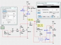
This obviously a far bit more complex, but you can pick and choose elements if you like any ideas:

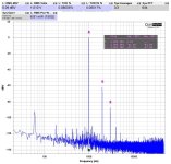
LTSpice gave me 0.015% distortion at 9V p-p. I would not expect it to be close to this in reality, but should still preform well.
I'v had good look with this CCS in terms of stability and seems to works well.
The JFET buffer make it easier to drive (input capacitance) and allows a smaller input cap to be used.
The AC feedback maybe a little much as 1000u output cap is more than enough into 150ohm not to roll off. But it does make it easier to set gain via R4.
Just thought I'd float some ideas around 👍
Last edited:

Thanks, I'm a believer in beauty in simplicity, if it works with acceptable specs then that's a win-win in my book.
Here is the latest version with Relay delay.Did someone did a PCB layout based on post no.10 ? Maybe I can do one (not this weekend) and also add the power on delay circuit from post no.7
I tweaked and changed resistors.
There is higher gain to suit 300/600 Ohm headphones.
Higher gain means higher distortion, but it is still rather low for such simple circuit.
Yes, it drops right in.Perhaps it would be worth trying the IRF520 in place of the 610.
It should drop right in....
There was a tiny bit more gain. And the output node was lower, 12.7V.
But distortion was somewhat higher, so I stick to IRF610 for this amplifier.
I am waiting for someone to make a PCB. I cant do it.
BD140 can take 12.5 Watt. 2.7 Watt should not be a problem, I think.
But MJE15031/29 for a TO-220 should be an secure option.
BD140 can take 12.5 Watt. 2.7 Watt should not be a problem, I think.
But MJE15031/29 for a TO-220 should be an secure option.
The dissipation will be (24V * 0.223ma) / 2 = 2.676W for both U2 and U3, assuming bias is set to 12V.
lineup: have you simulated with a JFET buffer? it seems to bring down distortion (unless that's what your after) and help with ripple rejection.
lineup: have you simulated with a JFET buffer? it seems to bring down distortion (unless that's what your after) and help with ripple rejection.
I set up a very similar circuit a while ago, it lacked power with speakers but sounded damn good with my headphones! strong 2nd harmonic is a good sound👍
Are you referring to your schematic above? That indeed simulates very nicely.I set up a very similar circuit a while ago, it lacked power with speakers but sounded damn good with my headphones! strong 2nd harmonic is a good sound
The BD140 can only dissipate 1.25W in a maximum ambient of 25C. It will need a heatsink.I am waiting for someone to make a PCB. I cant do it.
BD140 can take 12.5 Watt. 2.7 Watt should not be a problem, I think.
But MJE15031/29 for a TO-220 should be a secure option.

This looked like it would be fun to try on breadboard and after a couple of screw ups, I realized I had a mistake in connecting Q2 which I had replaced with BC560. I used the schematic in post #10 across a 150R load. I wasn't sure what input/output target to use, so I just set it to output 1V, which took 0.4V input to reach. BD140 was quite unhappy without heatsink, going over 70C until I got heatsinks on and then everyone got along nicely. I tried both IRF610 and IRF520 with no meaningful difference between them. If I drop down to a few hundred mV input (0.5V out), THD drops to below 0.05%. I wasn't sure how much current would be going through 3R3 so I used 3W. On bench supply, it starts out pulling around 170mA and goes up to 250mA as it warms up (+24V or 6W draw).
Thank you lineup for a fun exercise!
Cheers! 👍


Thank you lineup for a fun exercise!
Cheers! 👍
Hi Folks,
I have just finsished a few minutes ago a PCB for this Headphone amp, it's not the smallest but it's for fun, size is 96mm x 68mm. These PCB are for 1 channel. Q1 and Q2 must be attached to a heatsink. The schematic is per post 26 for higher impedance headphone (300/600 ohm). R5 is 1W and the rest 1/4W.
If I understood well the relay will be activated from when the 24v is applied and after a small delay the relay will become inactive.
Here are the files including the non-tested Gerber files.
Attachments

Last edited:
Hi,
P1 volume was very small and useless on my PCB therefore please find attached another set of Gerber without P1 and also a third Gerber without P1 and including a ground plane around the audio section.
P1 volume was very small and useless on my PCB therefore please find attached another set of Gerber without P1 and also a third Gerber without P1 and including a ground plane around the audio section.
Attachments
I think a bit more beefy U2 would be good. In Spice, e.g. the NJW0302G works well.
https://www.mouser.de/datasheet/2/308/NJW0281_D-1813438.pdf
The "profane" TIP36C does as well.
https://www.mouser.de/datasheet/2/308/NJW0281_D-1813438.pdf
The "profane" TIP36C does as well.
Last edited:
Adding input resistance (R2 10K) didn't change result as it just required additional input to reach the same output. I did a very rough calculation for the power rating of R3 (3R3) given the draw I was seeing on my bench supply which was drawing 0.25A so assuming the entirety of this was passing through R3 (which it's not), R3 would be passing ~0.2W. R3 could be satisfied with a 1/4W resistor
Anyway, not satisfied with the discrepancy between my reading and lineup's sim, I did a proper breadboard build which draws 0.2A and removed the 1K resistor at output that was in one of the earlier schematic.
With a cheap, minimal heatsink on U2, it's well behaved and stays below 50C. We can't get into the FAB club unless we pass 50C

Still having fun. Cheers!
Anyway, not satisfied with the discrepancy between my reading and lineup's sim, I did a proper breadboard build which draws 0.2A and removed the 1K resistor at output that was in one of the earlier schematic.
With a cheap, minimal heatsink on U2, it's well behaved and stays below 50C. We can't get into the FAB club unless we pass 50C
Still having fun. Cheers!
Attachments
- Home
- Amplifiers
- Pass Labs
- ZEN Amplifier Mini with IRF610 as Headphone Amplifier for 32 Ohm