The initial PCB was a small victory, although I need to fix the footprints for the jack and pot, the channel layout works well and the performance was pretty much the same as perfboard build.
I'll test the timer circuit next and populate the second channel before giving it a listen but still having far more fun with this than you would think to get from so few parts.
It pulls 210mA @ 24V. PCB is 100mm x 100mm. Schematic is from post #24. Active parts are BC559B, BD140-16 and IRF520. Measurements are taken with a 150R load resistor on the output.
Cheers,
Stephen

I have done simulation.
And I found the time capacitor should be 100uF .. not 22uF.
This gives like 5 seconds delay. Which is enough to charge the 1000uF capacitor.
And I found the time capacitor should be 100uF .. not 22uF.
This gives like 5 seconds delay. Which is enough to charge the 1000uF capacitor.
Last edited:
I have tweaked the circuit further. Lots of changes.
This version is for 32 Ohm, but I think it will work alright with other impedances.
Bias is increased to 300mA, and the output is at 12.2V.
Input capacitor is now film 1uF.
Relay capacitor is 100uF. Gives delay 5 seconds.
There is no new parts, so I think it will work with same PCB.

This version is for 32 Ohm, but I think it will work alright with other impedances.
Bias is increased to 300mA, and the output is at 12.2V.
Input capacitor is now film 1uF.
Relay capacitor is 100uF. Gives delay 5 seconds.
There is no new parts, so I think it will work with same PCB.
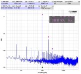
This is the result of Fourier simulation.
As can be seen there is H2 dominant.
And H3 is 35dB down and the rest very low.
This is typical for Nelson Pass ZEN amplifiers.
It is the way he likes it. Makes amplifier 'sing'.

As can be seen there is H2 dominant.
And H3 is 35dB down and the rest very low.
This is typical for Nelson Pass ZEN amplifiers.
It is the way he likes it. Makes amplifier 'sing'.
This obviously a far bit more complex, but you can pick and choose elements if you like any ideas:
View attachment 1287373
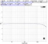
LTSpice gave me 0.015% distortion at 9V p-p. I would not expect it to be close to this in reality, but should still preform well.
I'v had good look with this CCS in terms of stability and seems to works well.
The JFET buffer make it easier to drive (input capacitance) and allows a smaller input cap to be used.
The AC feedback maybe a little much as 1000u output cap is more than enough into 150ohm not to roll off. But it does make it easier to set gain via R4.
Just thought I'd float some ideas around 👍
Completely untested and I don't have the Spice sim so if you're feeling brave and/or bored ...
Schematic used
Attachments
With all due respect to @lineup as the OP, I had a batch of @mr_zener Zen HPA boards fab'ed and after a small misunderstanding with myself (BD140 instead of BD139), got the following results finally. Quick post so I'll upload a picture of the board later but it's essentially the linestage as above with the muting relay, input pot and output jack.
Thanks to mr_zener for his design!
Cheers,
Stephen
Thanks to mr_zener for his design!
Cheers,
Stephen
Attachments
- Home
- Amplifiers
- Pass Labs
- ZEN Amplifier Mini with IRF610 as Headphone Amplifier for 32 Ohm