Wow, I feel like I've already screwed up my chances at a descent ZAPpulse amp... My PSU consists of a pretty standard 500VA transformer connected to a schottky bridge, going through two RIFA PEH200 in parallel.
Any tips on improving it without rebuilding the whole thing? I don't have the amp units, so I haven't been able to listen to it yet, but you're probably better judges of that than me anyways...
Any tips on improving it without rebuilding the whole thing? I don't have the amp units, so I haven't been able to listen to it yet, but you're probably better judges of that than me anyways...
Thankyou Chris: Very interesting information. Going by the spec's it would appear that the only weakness of a 4 pole cap is the output impedance in the lower bass area (hence the need for very short heavy gauge wire), but, this can be resolved by paralleling 2 or more 4 pole caps together.
Chris, the diagram does not look quite right? I assume that the negative input connects to the two joined negative poles and the negative output connects to the other two joined negative poles. Is that correct?
Chris, the diagram does not look quite right? I assume that the negative input connects to the two joined negative poles and the negative output connects to the other two joined negative poles. Is that correct?
Hi KLe,
I'm assuming you're looking at their first example, where the impedances don't end up adding together, and they only show you the input/output for the positive leads?
I'd make the same assumption as you, just connect the negatives the same way, both inputs tied together will be your input and both negative outputs tied together will be your output.
Now are the T-network caps from BHC the same internally as the Jensen's.. I assumed it is but they're your caps to explode, proceed with caution.
BTW I'll be using 11.4awg pure copper litz wire with mine, cut to identical lengths and not much longer than they need to be.
I'll have to get the data sheet for the cerafines I got (just came in yesterday) and see how they measure up to the T-networks.
I see it's no problem to parallel them with a 2 pole cap too, maybe I'll try them in conjuction with the Cerafine caps too.
I have to say, these Cerafines are about ~3.5X the size of the 8200uF 71Vdc Elna's I took out of my old commercial amp. They don't look like raisins so they couldnt' have been sitting on the shelf all that long 🙂
Novec, sounds like a nice supply to me. I think you're cheapest /biggest improvement would be to use a second schottky bridge.
Cheers,
Chris
Hi Chris: Yes, I am referring to the first example. I wonder if Lars can answer this question for us? Do you expect any benefits by paralleling them with a 2 pole cap. I am not sure that the output impedance, storage capacity will be increased, but maybe the big plus is filtering. What are your thoughts?
Hi Lars: Chris and I need your advice ... Are the T-network caps from BHC the same internally as the Jensen's? I do want my BHC caps to explode (should I try/do this?).
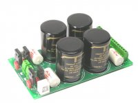
Hi Novec: Here's an excellent PS design that shows the use a second schottky bridge improvement, that Chris has written to you about. (see http://www.audiocircle.com/circles/...ame=gallery&file=index&include=view_photo.php ). You can use the 10,000uF 63V BHC Aerovox T-Power 4 pole capacitors, if your budget can stretch in this PS design.
Hi Lars: Chris and I need your advice ... Are the T-network caps from BHC the same internally as the Jensen's? I do want my BHC caps to explode (should I try/do this?).
Hi Novec: Here's an excellent PS design that shows the use a second schottky bridge improvement, that Chris has written to you about. (see http://www.audiocircle.com/circles/...ame=gallery&file=index&include=view_photo.php ). You can use the 10,000uF 63V BHC Aerovox T-Power 4 pole capacitors, if your budget can stretch in this PS design.
Hi Chris: Are using or have you tried the 0.22uF PP 250V/400V caps shown around the bridges?
My experience has been that without them the Zappulse 2.3SE sounds bright and edgy, although fast, but with them the Zappulse 2.3SE is so much quieter and has a much more earthy/organic/real sound, though still fast. At this stage I will not be removing them. I used 0.22uF PP 250V caps mains caps, which are cheap, less than a A$1.00 each.
My experience has been that without them the Zappulse 2.3SE sounds bright and edgy, although fast, but with them the Zappulse 2.3SE is so much quieter and has a much more earthy/organic/real sound, though still fast. At this stage I will not be removing them. I used 0.22uF PP 250V caps mains caps, which are cheap, less than a A$1.00 each.
Hi,
Actually I didn't have that supply in mind at all, the dual bridge rectifier thing has popped up everywhere, Randy Sloan's book, TNT audio.com, zerodistortion.com....hell, it's even been put to use in my old commercial junker, believe it or not! I think his supply sounds alright so far though, these are all little extras... it's not like you _need_ it.
Depending on your choice of rectifier it can be a real cheap mod to make. If you're using schottky's though it probably won't be.
Kle, I think they should be the same, I was only trying to make a point, and maybe scare you a little bit.. don't just take my word on it! 🙂 Just have some safety glasses on when you plug it in.
Oh and I think you meant to say "_don't_ want to explode". They also keep saying "fire" instead of "four" in that data sheet.... whenever I see something like that I have to question its technical merit.
I expect a very small difference paralleling Cerafine's before the T-networks as their impedance curves must combine giving it a different characteristic. I'd think it would be a change for the worse, kind of like ******* upstream, that is assuming that the T-networks will have the better sound at all. I also think the increased filtering will swamp any minor differences it would have had otherwise, but I guess now I owe it to the forum to try what I can with them. You're going to have to be the one to tell us what paralled T-networks are like.
I've never heard of anyone mixing caps like that anyway, and as a bonus if I don't hate it, I'll keep them all in there for the extra reserve.
Regards,
Chris
10 months ago I bought BHC T-network and SlitFoil capacitors to use them in the UB-Audio NT-E power supply, all 10000uF, 63V.
I talked to the technician of the store I bought the capacitors at because at first I wanted to use 4 pcs. T-Network caps in each supply (2 per rail). I also have to explain that in this supply the T-Networks are in series one after the other (see attached picture). The technician said that they already had tried all combinations (4x SlitFoil; 4x T-Net; 2xSlitFoil+2xT-Net; 2xT-Net+2xSlitFoil). I asked him about his ranking for these combinations and he told me that the best sound of all was the combination 2xT-Net+2xSlitFoil. Also note that this combination should not be used after the Jensen document a view posts above! On second place came the combination 4x T-Net, 3rd place was 2xSlitFoil+2xT-Net and 4th was 4x SlitFoil. I didn't really believe him because my first thought was that the SlitFoild should come first and afterwards the T-Nets and so I installed only one T-Net per rail up now.
Summarizing this post it would be really interesting if the combination 2xT-Net followed by 2x Cerafine could also be tested according to this technician the best sounding combination.
By the way don't blame me now for posting this here also but it seems the most interested people for SlitFoils and T-Nets seem to gather here I have still 4pcs. SlitFoils and 4pcs. T-Nets lying around (all 63V, 10000uF) because I wanted to build 4 amplifiers and than only built 2 so I still have these left. If anyone is interested contact me by PM.
Attachments
Hi,
Just to be polite, maybe a mod could move all this cap stuff into it's own thread? We've hijacked this one (good intentions and all).
You bet, I'll give all possible combo's a try and give a full report. To be fair I'll have to let each combo have enough time to break in.
What puzzles me is all the times I've read that you can combine the two technologies to make a four-pole-slit-foil. They must have tried it, why aren't they selling it?
As far as what they recommend comes first I think it's just a case of marketing. /
Has anyone tried them with the "current limiting" resistors as seen in the data sheet? I have to wonder if that node would be prone to ring without them? Normally this isn't an area you'd want to limite the current (ten gauge wire etc), and by-passing the rectifiers does that job far more efficiently than a series resistor could.
Regards,
Chris
>>What puzzles me is all the times I've read that you can combine the two technologies to make a four-pole-slit-foil.
>>They must have tried it, why aren't they selling it?
It also took me a while to understand this sentence in the T-Net data sheet. First you think of they mean you should combine a SlitFoil with a T-Net to get optimum results but actually they want to say with this sentence that the T-Net is a combination of 4pole and SlitFoil. Yes the T-Net is a SlitFoil capacitor in a 4pole configuration so no worry why they don't produce such as cap, they do.
Yes, I also support the idea of moving part of this thread.
Should read something like "Comparison of caps: T-Net and Elna Cerafine"
Should read something like "Comparison of caps: T-Net and Elna Cerafine"
Hi,
Are you sure?? Got some inside info on that? They only ever said it "can" be done...which kind of implies that they aren't.
You'd think they'd really be marketing that if they were. "The ultimate slit foil, newly improved..."
Not a great title as I haven't ruled out acquiring other caps; Somewhere, someplace, there's a proud owner of black gates on their death bed...
Maybe something like "Any difference between high grade caps? Tune in next year..."
Cheers,
Chris
KLe: If you mean a second bridge as in one for each voltage (+60 to ground, and -60 to ground), I have that. Apart from all the tiny caps and the resistors at the end (R1/R2), this looks just like mine.The ZAPpulse already has the resistors and last caps incorporated, doesn't it?
I'll use standard polypropylen mains caps around the bridge, like you're suggesting, KLe. I guess that's the way to go for the other little caps, too?
BTW, my RIFA caps are dual 15mF connected to each voltage rail, totalling four per channel.
I'll use standard polypropylen mains caps around the bridge, like you're suggesting, KLe. I guess that's the way to go for the other little caps, too?
BTW, my RIFA caps are dual 15mF connected to each voltage rail, totalling four per channel.
You ask if I have some insider infos proofing that the DNM (BHC) T-Net cap is a combination of 4pole and SlitFoil technics?
Yes, I have poof but it seems not to be insider info.
Just have look at their homepage http://www.dnm.co.uk/capbhc.html.
Their you can read:
"This T-Network capacitor uses a combination of T-Network and Slit Foil technology to produce the ultimate audio capacitor. It is a typically ultra-reliable BHC electrolytic with performance exceeding even the most expensive specialist electrolytics"
Greetings
using_e
Hi,
Thanks, I hadn't seen that page before.
BTW I was joking about black gates, but I would also like to test these against your usual properly selected industrial type cap.
I'm going to go revive an old power supply thread and continue this discussion there... along with a few other things.
Regards,
Chris
Hi Chris: Sorry for the delay in replying, but, yes I will try the paralleling T-network caps and let you know the results? I would really like to know that it can be done before I do it though. I have sent Lars an email, asking him for his advice, so, hopefully he will reply soon?
Hi novec: Yes, a bridge for +60 to 0 (ground) and a bridge for 0 (ground) to -60V. The resistors at the end are bleeder resistors (not important to sound quality) to discharge the caps when you turn the amp off. The 0.22uF PP mains caps around each bridge I found to be very important. Yes, The 0.1uF PP caps between +60 to 0 and 0 to -60V can be soldered directly on to the AC bridge pins. I would >10 hours breakin. Post the results, once done and evaluated.
Hi using_e: Thankyou for the information. Unfortunately, it doesn't show anything about paralleling them, but, terrific information nonetheless.
Hi novec: Forgot to inform you of the following. I was using a single 500VA transformer, but I am now using a 1KVA transformer. The improvement in sound using the 1KVA compared to using the 500VA was quite noticeable. But, before I changed to the 1KVA transformer I was already using the 0.22uF PP caps. Hope this helps?
All of this definately helps, KLe! I'll try leaving the 500VA toroids in there for the time being, though. As you can see from the design layout, there's no room to spare, and I don't feel like making a whole new box quite yet...
Can anyone spot my design flaw? Yes, I know... The caps... The +60V stretch from the two front caps will be about 15 cm, but will it really matter? There isn't enough room to have all eight on a row across the amp, and I'll use as heavy gauge cable as the ZAPpulse can take.
An externally hosted image should be here but it was not working when we last tested it.
Can anyone spot my design flaw? Yes, I know... The caps... The +60V stretch from the two front caps will be about 15 cm, but will it really matter? There isn't enough room to have all eight on a row across the amp, and I'll use as heavy gauge cable as the ZAPpulse can take.
I'm a little uncertain about whether to ground the PSU, signal or both on the ZAPpulse 2.3SE, or leave it all ungrounded. And if grounding is best, is the ground filtering on the mentioned PSU (this one) is adequate? My CD player isn't grounded, that might be a point.
I know this is starting to go off topic, but please don't kill me 😉
I know this is starting to go off topic, but please don't kill me 😉
Hi,
Apperently there's no sure answer of what will work 100% of the time as far as grounding schemes.
You've seen one poster report not grounding anything for a hum free system, that's believable. It's not desirable though, should there ever be a short..
I think the ideal situation would be only the amp being earthed. Then you've got it where it matters, and no loops.
Read Rane note # 151 and #110. That'll shed some light on it all.
I think you should ground both signal and chassis, usually you ground the signal shield at the source, but that's not guaranteed to be hum free. You could also provide a ground lift switch just in case there is hum. Signal ground should be right on the case at the point of entry.
You can also use a resistor to lift the signal ground from the chassis ground if you have hum problems, or you can use a small value capacitor, which will present a very low impedance to RF, yet a fairly high impedance to the low ~60hz hum frequency.
That method seems to be the recommended one for any unbalanced input (all your RCA's).
For balanced inputs they recommend grounding the shield directly to the case at the point of entry without any kind of lift circuits.
If you have problems though, as the Rane note say's, may the force be with you, expect many hours of experimenting.
In the same Rane notes you'll see just about every possible interconnect configuration you can try in case you do have problems.
I think your layout could possibly be further improved. I dont' see the caps themselves as being the biggest problem, but rather that you're passing the mains through the length of the case, and that your modules are right beside them. (HUMMMMMMMM).
I think what you should do is take that layout and flip it right over. Have your Xformers at at the back right at the mains input so they dont' run through the case and you're ahead of the game already.
Then your modules will be at the front of the amp well away from the mains. You could possibly use that channel you have in the center of the case as a conduit for the signal wires, shielded twisted pair.. yer laughing! You also won't be running your volume controls next to the PSU..
I don't think the 15cm run is too long as long as you use a good gauge as you said. What I would do is make sure all the leads are the same 15cm.
Regards,
Chris
- Status
- Not open for further replies.
- Home
- Amplifiers
- Class D
- ZAPpulse 2.3SE vs. 700XE