0.1 mv will work and not cause any undue heating of the semi's after that you can raise it as you like I am thinking...😉
i generally set them using the current meter. perry has a little interactive simulation. back them off to zero, then slowly raise to the point that current starts to barely draw, and repeat.
Got it... So since it a 4 channel amp, I thinking turn all 4 pots down, start with one and bring it up until the current draw is 1/2 amp, then do this to the remaining 3 channels so I get a total of 2 amps idle?
Originally Posted by Perry Babin
As was suggested, you need to bias the transistors. If you have a power supply with an amp meter, set it as is shown in the following demo.
http://www.bcae1.com/temp/ausettingbias.swf
Originally Posted by Perry Babin
As was suggested, you need to bias the transistors. If you have a power supply with an amp meter, set it as is shown in the following demo.
http://www.bcae1.com/temp/ausettingbias.swf
Last edited:
i pay less attention to how much it is, as long as it is in a good range at idle. it could be 1.5-3a idle typically, but anyways, it goes like the demo x4. back all off, like you mentioned, and raise them until the current just starts to pick-up. sometimes i do it a few times to be sure. then move to the next, and repeat until all are done.
Think I'm finished...
On channel 3 which is rear left, I replaced the MPSA06 near the finals, replaced a TIP102 and 107 Which are part of the finals. Pulled a TIP35C but it was good.
I really don't think the problem was in the final area as everything I pulled was good. So on to the next...
I replaced the 2N6715 and 10uf 50v, part of the PWM, don't think they were bad.
Pulled the 4700uf 50v caps, they are good.
Around the NAND Gates, I replaced two MPSA06 and one MPSA56, again, don't think they were bad.
Replaced the two J109 on channel three, they weren't bad but I could smell capacitor liquid. Cleaned it the best I could.
Replaced the two NAND Gates
Replaced 12 OP-Amps, No more static noise now.
OK, When I pulled the CENU-07 and CENU-57 from channels one and three, I did not use enough heat and pulled small traces off the board. Spent about 4 hours repairing them
Idle current is back to 2Amps.
Adjusted bias so now Idle is about 2.2 amps.
Not sure what fixed it, maybe cleaning the rest of the leaky cap off the board?
Now just have to put it all back together😎
Attachments
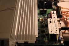
These are the traces that pulled and ripped off the board.
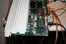
Also when cleaning this transistor and resistor came off and the pads were very corroded. NOT FUN!!!
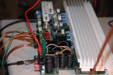
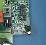
Also the semi and cap I changed by the PWM
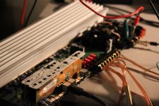
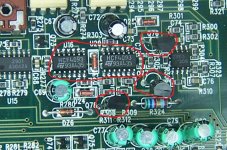
And the Semis plus NAND Gates.
😎
Also when cleaning this transistor and resistor came off and the pads were very corroded. NOT FUN!!!
Also the semi and cap I changed by the PWM
And the Semis plus NAND Gates.
😎
Attachments
Last edited:
OK, For testing, I pulled two of the four 4700uf caps out. When I reinstalled them, it went back to protect mode. Every thing I've read and most Soundstreams use 1000uf caps for filtering. Is it ok to use 1000uf caps on this Zapco?
Well I put in 4 new 1000uf 50v caps and it turns on with no faults and no big surge of current. Now I have to push it to almost clip to see if I made any mistakes, so far I've run it to the limit of one of my power supplies and the wife yelled at me...OOOPPPPs. Its a 12 amp supply.
Thanks all about the bias adjust info, really works...😀
Thanks all about the bias adjust info, really works...😀
not sure about pushing it ti clip yet. you may encounter a little noise there, since you now have less that a quarter of the capacitance at the rail, and some of the lower frequencies may come through, like the a/c ripple (alt whine) which might come through the power supply. not sure, but it is a possibility. are you planning on going back to larger caps? did you find a bad one?
They are old and they ohm out ok but with them in circuit the amp struggles to start. Plus these boards are so fricken delicate, when I was pulling two of the caps, two of the circular feed through that sits in the hole came out. The positive rail has the main trace in one of the inner layers and that sucks to fix. The ripple with the old caps was about 30 mv, now its down to 2 or 3 mv. I may get larger value caps at a latter time.
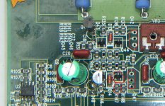
How come the old Soundstream reference 1000s only has two 1000uf 50v caps for its rail? See pic...🙄
How come the old Soundstream reference 1000s only has two 1000uf 50v caps for its rail? See pic...🙄
Attachments
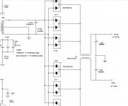
Most amps (especially those with inductors between the rectifiers and the caps) could use less capacitance. The 1000S didn't need more than what was used.
soundstreams are less "typical" between the inductor, and how the power supply is setup, there is less need for the larger caps. you may not need them, but i am unsure how much of a difference it is going to make on the output circuitry. i, personally would go back to the 4700's
(forgot to push "post" this afternoon, lol)
(forgot to push "post" this afternoon, lol)
I never knew that's what those were for. Thanks for pointing that out.
I Wonder why the heck zapco didn't use inductors?
Would have used less real-estate.
Yes I will put new ones back in. Every time I touch this board it feels like I'm doing brain surgery.
Now to find some inserts to replace the missing ones. I looked in my PACE kit and they are too small.
Thanks guys for putting me back to work😀
just different designs, i suppose. it was probably cheaper to just use larger caps, as well as having more stored rail power. than there is the fact that they can get hot, and have more rigid vibrating mass. i have seen many inductors that have fallen loose from the board. mainly larger class-d amps. your guess is as good as mine.
 just a side note: i would use a different amp schematics for making comparisons to the zapco. don't think you can get x-tant schematics, whic seem to be similar, but the circuitry does somewhat resemble phoenix gold (aside from case appearance being close to the m-series, lol. the 90's soundstreams always seem to have more different things going on than other typical designs.
 I wish zapco would let loose of the schematics for the discontinued models but I guess they want to sell the newer stuff.
Just a short question!
As you have a Z400 on your table, can you tell me how the fan is connected?
Because there are four contacts for it.
Mine came without the fan. It was broken off it's frame and gone.
Thanks in advance!
Julian
As you have a Z400 on your table, can you tell me how the fan is connected?
Because there are four contacts for it.
Mine came without the fan. It was broken off it's frame and gone.
Thanks in advance!
Julian
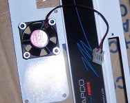
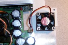
I tried it both ways and it just reverses the fan. I think it blows air into the unit as there is dust on the 16v caps from that side.
- Status
- Not open for further replies.
- Home
- General Interest
- Car Audio
- Zapco Z400C4-SL... Not Again!