Received amp with blown power supply and outputs rebuilt PS board and tested without outputs and rail voltage was 70 volts. Rebuilt output board and amp draws excessive current and rail voltage is only 20 volts. High side and low side outputs are receiving gate signals but there is no rail to rail oscillation. It shows a small oscillation on scope then stops.
Have you tried to get a diagram from Zapco. It's hit and miss but they will sometimes send them.
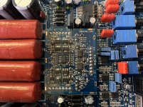
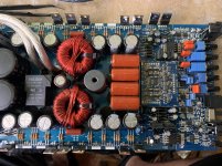
Post a photo of the component side of the entire main board and the component side of any driver boards if no one can help.
Post a photo of the component side of the entire main board and the component side of any driver boards if no one can help.
Did you confirm that the drive signals were driving fully back to the rail votlage?
How much current was it drawing when the rail voltage was only 20v?
Confirm that the rail voltage was positive AND negative. You weren't clear about that.
How much current was it drawing when the rail voltage was only 20v?
Confirm that the rail voltage was positive AND negative. You weren't clear about that.
Rail voltage is positive and negative and maxed out my 20 amp power supply. Outputs are receiving gate signal off the positive and negative rail.
Did you confirm that the drive signals were driving fully back to the rail voltage?
What was the amplitude of the drive signals?
Did you confirm that the signal was strong by loading the g-s of the output FET pads with a capacitor (~0.01uf)?
What was the amplitude of the drive signals?
Did you confirm that the signal was strong by loading the g-s of the output FET pads with a capacitor (~0.01uf)?
The outputs were in and are in when I confirmed the gate signal. Amp doesn’t function without outputs in the amp.
In reference to oscillation on the outputs. Before I installed all new outputs the power supply after rebuilding it was producing +-70volts for rails. I rebuilt the driver board installed new outputs and now rail voltage is only 23volts with no oscillation on the drain of the outputs and maxes out my 20 amp power supply. Im confused as to why the amp isn’t producing 70 volts for rail voltage.
I was saying the outputs can’t function meaning oscillation if there are no outputs in the board.
The high current draw is dragging the power supply down.
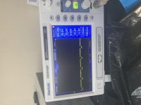
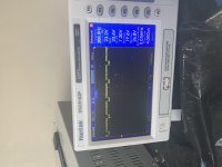
Remove the outputs. Drive a 50-100Hz signal into the amp. Confirm that the drive signal is driving fully back to the rails. Bear in mind that we don't know where the rail voltage is if you don't post a photo of it along with the drive signal.
This works best, most reliably, if you load the FET locations (one per bank) with a capacitor of about 0.01uF.
With the outputs removed and the capacitor between gate and source there is a drive signal present.
I can't judge whether the drive is good or bad without seeing it. Remember, I need to see the rail voltage as well.
For some reason I’m not able to upload the photos of the signal. I’ll keep trying but I believe the issue is between the lm211 and tl072. Before I took out the outputs the 15 volt regulators had 6 volts on them. So I removed the 5 volt regulators and the 15 volt regulators were reading like they should. I’ll try again to upload the photos.
I discovered with all outputs in if I remove Q7 & Q11 I get rail to rail oscillation on one side of the amp. And if I put in Q7 & Q11 and remove the driver transistors I have the correct signals on all pads and is identical to the side of the amplifier that is oscillating. I’ve narrowed it down to this side of the driver board and this side of amplifier.
Are you sure it's Q7 and 11?
Do you have to remove BOTH 7 and 11?
Are the gate resistors for Q7 and 11 within tolerance?
Do you have to remove BOTH 7 and 11?
Are the gate resistors for Q7 and 11 within tolerance?
Yes, I have to remove both to get rail to rail oscillation on the outputs on the other side of the amp. Q7 is a 2D transistor and Q11 is a 1D transistor.
- Home
- General Interest
- Car Audio
- Zapco Z-2KD Amplifier