I recently acquired a Studio 500 amplifier.
I've had some difficulty searching for a service manual for this unit.
I did reach out to Zapco earlier today to see if they have one available they are willing to share.
I've not tampered with anything on the board so far, just removed a couple heat sink clamps to test the voltage regulators.
I've powered the amp on
No protect light, very little DC offset (.02)
No sound out.
If I crank the gain knob the clip indicators will slowly flicker as I adjust the gain.
There is no sound out, at all.
I've got +15 on pin 1 and 3 of tip31 and -15 on its counter part
I've got lots of photos.
There are not any muting relays
I will clean my post up, I apologize I had finished it in haste before I lost my text I had typed
Zapco has been releasing some diagrams. It would be easier to troubleshoot if you wait (at least a day or so) to see if you can get it.
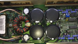
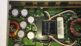
Link to or post photos, please. One photo of the inside would be good to start.
Link to or post photos, please. One photo of the inside would be good to start.
Here are a couple photos.
Attachments

Last edited:
Zapco was kind enough to send me a copy of the schematics.
I noticed there are two SMD leds that illuminate when I power the amp on
I noticed there are two SMD leds that illuminate when I power the amp on
Are you going to post the diagram?
The LEDs could be part of a constant current circuit but without seeing the diagram, that's just a guess.
The LEDs could be part of a constant current circuit but without seeing the diagram, that's just a guess.
Hi Perry,
Which diagram would you like to see? It's broken down in to sections.
I have separate attachments for input, layout, output, and supply
The lay out does not have the schematic, but the others do.
Can I attach PDF files here?
Which diagram would you like to see? It's broken down in to sections.
I have separate attachments for input, layout, output, and supply
The lay out does not have the schematic, but the others do.
Can I attach PDF files here?
let me know if this link works
https://www.dropbox.com/sh/adls0jqav6cdge8/AACRdXdxfOyu9eXdzek8uXEMa?dl=0
The one LED is in the isolated muting interface, the other in the linearized isolated feedback circuit for regulation, both in the supply schematic
https://www.dropbox.com/sh/adls0jqav6cdge8/AACRdXdxfOyu9eXdzek8uXEMa?dl=0
The one LED is in the isolated muting interface, the other in the linearized isolated feedback circuit for regulation, both in the supply schematic
Just an observation that they are illuminated. I do not know if they would be illuminate for functionality and to show power or fault
I think they show that the corresponding circuit is active (working correctly). I would expect there to be a delay on the muting LED.
I'll power it up and see if there is a delay.
Is there any other basic trouble shooting you would suggest?
Is there any other basic trouble shooting you would suggest?
Operate all pots and switches through their entire range to see if audio will play through intermittently.
There is only one pot, for gain. The only thing that changes is the clip lights will flicker before going solid the higher I turn the gain up.
Set your meter to AC voltage, lowest range if not auto-ranging. Drive a signal into the amp and turn the gain until the clip LEDs just light up. With the black probe on a non-bridging speaker terminal. Touch the red probe to the various large blue 0.2 ohm resistors. Do you read more than a fraction of a volt on any of them?
Oops, I'll have to redo this step. I only measured AC voltage on the output with a 1khz tone and read .6V
I'll follow the correct steps later on today
I'll follow the correct steps later on today
I tested the SG3525
1. -9.43
2. -9.40
3. -11.98
4. -11.84
5. -9.83
6. -8.18
7. -9.94
8. -7.06
9. -10.26
10. -12
11. -9.14
12. -12
13. 5.25
14. -9.16
15. 5.25
16. -6.80
1. -9.43
2. -9.40
3. -11.98
4. -11.84
5. -9.83
6. -8.18
7. -9.94
8. -7.06
9. -10.26
10. -12
11. -9.14
12. -12
13. 5.25
14. -9.16
15. 5.25
16. -6.80
- Status
- Not open for further replies.
- Home
- General Interest
- Car Audio
- Zapco Studio 500 repair