Member
Joined 2009
Paid Member
50EH5, 50C5?
I built one of the 1st…
yeah, that's the type of thing ! - simple single device.
I read more good things about the Hawthorn Audio forum spud - quite popular and lots of photos of it - I'll draw up a schematic.
Attachments

Member
Joined 2009
Paid Member
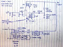
Here we go. From what I've read on the internet this design was originally by a chap called Jef Larson. Seems he was a fellow DIY'er. The schematic was improved on and tweaked by some other chaps, a Jerry Curtis and a Terry G but I think the main approach is what I've captured here based on all the tid-bits I can find. It's simple and looks like a good start.
Smoking Amp - some corn on the cob would be nice !
Smoking Amp - some corn on the cob would be nice !
Attachments
Last edited:
Old Milwaukee and Spud Light to go with that corn on the tube.
That 6CL6 maybe could use some more gm to operate off of 1 V input.
6HB6 12GN7 11HM7 TFH ....
Dual section tubes: 6AH9 6GF7 6FM7 6FY7 ....
That 6CL6 maybe could use some more gm to operate off of 1 V input.
6HB6 12GN7 11HM7 TFH ....
Dual section tubes: 6AH9 6GF7 6FM7 6FY7 ....
Member
Joined 2009
Paid Member
So we have to worry about the transconductance, the gm. How much gm do we need ?
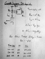
Not sure if my math is clear (attached).
Here's how I'm thinking. I have an OPT with a turns ratio of N between primary and secondary. A voltage signal applied between the control grid and cathode produces a current swing through the anode equal to the input voltage swing multiplied by the transconductance.
The current swing through the anode flows through the primary of the OPT and is reflected into the load according to the turns ratio. For example, a turns ratio of 10 means that 100mA change in anode current will generate 1A of swing through the load.
If I want an input voltage swing of 1V to produce a current swing of 1A through the load then the transconductance of the control grid (wrt to the anode) must be the reciprocal of the turns ratio.
The OPT I have can be configured for 10k, 5k or 2k5 into 8R and from this the turns ratio can be determined. It shows that the tube needs a transconductance of at least 29mA/V.
This is a bit of a simple analysis and other constraints will apply e.g. the voltage swing at the Anode must not exceed the normal operating range for the tube so there will be a power limit etc. so a 1A swing in the load is probably to optimistic. This means that the target minimum transconductance will be lower. If I want 2W(rms) into an 8R load then I need a peak current swing of 0.7A so the transconductance I need is more like 20mA/V and for 1W (rms) I only need 15mA/V.
Does this sound right ?
Attachments
Last edited:
Sounds about right. Of course the delta V on the plate will be increased by the turns ratio from the load too. Class A pentode SE will get you around 1/3 to 1/2 of the Pdiss of the tube for output likely.
The 6CL6 is rated 7.5 Watt Pdiss and 11 mA/V gm at 30 mA idle.
An 11.5 Watt Pdiss 12GN7 has 36 mA/V gm at 28 mA idle.
A 10 Watt 6HB6 has 20 mA/V gm at 40 mA idle.
A 10 Watt 12HL7 has 21 mA/V gm at 25 mA idle.
A 10 Watt 12HG7 has 32 mA/V gm at 31 mA idle.
A 35 Watt 8417 (expensive, rare) has 23 mA/V gm at 100 mA idle.
A 10 Watt 8233/E55L (expensive, rare) has 45 mA/V gm at 50 mA idle.
A 30 Watt 35LR6 has 16 mA/V gm at 140 mA idle.
A 30 Watt 42KN6 (dual section type) has 16 mA/V gm at 100 mA idle.
(single section version more like 14 mA/V gm at 100 mA)
Could be some comparable Russian tubes maybe?
The 12GN7, 12HL7, 12HG7, 8233 and maybe 8417 are frame grid, which won't like positive grid excursions (tiny grid wire meltdown). (use a silicon clamp diode from cathode to g1 to protect)
Last edited:
Member
Joined 2009
Paid Member
The swing at the plate gets really large at the higher turns ratio. Question is, do I need to keep the plate voltage above the (fixed) screen grid at all times ? and is there a difference in this regard between a pentode and tetrode ?
You want to use the lowest Vg2 that will give you a plate knee at the peak current needed. That will minimize g2 dissipation. 150 V on g2 will probably allow it to swing down to 60 V on the plate, depends on the tube (see data curves for knees). Check the final setup for Pdiss and g2 diss. at idle.
Tetrodes, I would expect, probably draw more g2 current and limit the plate V swing more. I would avoid them.
Unless you mean Beam tetrodes, which should work even better than a pentode for power output. But will likely have more 2nd Harmonic dist. than a pentode. Likely less odd harmonic than the pentode though.
10 K Ohm primary is probably the highest you want to go. Highest efficiency, but frequency response and availability getting sketchy up there or above 10K. A really small OT (like 5 watt) may be able to go to 15K Ohm.
Another option besides really high gm would be an input step-up xfmr., if the source can drive it. There are some inexpensive Edcor WSM and XSM xfmrs.
Last edited:
Member
Joined 2009
Paid Member
You want to use the lowest Vg2 that will give you a plate knee at the peak current needed. That will minimize g2 dissipation. 150 V on g2 will probably allow it to swing down to 60 V on the plate, depends on the tube (see data curves for knees). Check the final setup for Pdiss and g2 diss. at idle.
I have ordered four 6p15p tubes just in case they are useful. They look to have decent gm at around 15mA/V, decent headroom at Va 300V (max 330V) and Pa 10W (max 12W). I'll follow-up and look more closely at operating points - probably the closest option to Jef Larson's circuit.
Tetrodes, I would expect, probably draw more g2 current and limit the plate V swing more. I would avoid them.
Somewhere in my junk box I have four 6E5P tubes I've never used. These tetrodes have high transconductance, up around 30mA/V so they could be used with lower OPT turns ratio and hence require less voltage swing on the plate. That may suit them since they have a Va max of only 250V. Pa max just over 8W and g2 Pa max over 2W. Again, I'll need to dig out a data sheet and look at the curves for some suitable operating points.
I'm impressed by the performance that can be had from inexpensive sweep tubes. My favourites include 6LR8/6LU8 (same tube, different envelope) and 6GF7A. 5 kΩ plate load, 250-300 V B+, anode dissipation slightly above spec -> audio nirvana.
Tom
Tom
The Spud Kit | …hearing is believing
Terry G's kit...
Novar Spud: Novar Spud: 6LR8, 6KY8, or 6GF7A one-tube amplifier.
Terry G's kit...
Novar Spud: Novar Spud: 6LR8, 6KY8, or 6GF7A one-tube amplifier.
"Somewhere in my junk box I have four 6E5P tubes I've never used. These tetrodes have high transconductance, up around 30mA/V so they could be used with lower OPT turns ratio and hence require less voltage swing on the plate. "
Well, tetrodes could be wired for triode mode too. That would solve the speaker damping issue. I don't think they will work well in UL mode though, too much g2 current maybe.
Do your OTs have a UL tap?
The high gm tubes tend to use a lower voltage g2, so won't work with UL mode without some assistance (SS).
Member
Joined 2009
Paid Member
The Spud Kit | …hearing is believing[/url]
Terry G's kit...
That's the one that caught my eye - I've posted the schematic above.
Given that it's a proven concept it would be a low risk option to build - hence the 6P15P tubes I've ordered - Terry likes them - to be more accurate he has tried the SV83 and likes some of the qualities of that tube, the 6P15P is its doppelganger.
I would consider trying an emitter follower for g2 drive though as a possible change to Jef's circuit.
Do your OTs have a UL tap?
The high gm tubes tend to use a lower voltage g2, so won't work with UL mode without some assistance (SS).
No UL tap.
The 6E5P makes one of the most linear tubes out there when triode-wired. This is something I could explore, but as a triode the gain will be modest to say the least.
Hi Tom - 6LU8 and similar were ruled out - two devices per envelope - may as well build a two-stage SET. This project has to use a bulb with one device only. Just for the heck of it. And the response to the Spud Kit from Terry G suggests such a path can lead to VERY nice results.
Last edited:
Hi Tom - 6LU8 and similar were ruled out - two devices per envelope - may as well build a two-stage SET. This project has to use a bulb with one device only. Just for the heck of it.
Fair enough. I'm curious to see where you end up.
Tom
Member
Joined 2009
Paid Member
Whilst waiting for the 6P15P tubes to show up in the mail I'm going to see what I can get a 6E5P from my junk box to do.
I've got a Hammond 270DX on my experimenters chassis so I've wired that up. The 275-0-275 HT secondary goes into a full wave SS rectifier made from two Cree diodes (1.2kV rated), then a Hammond 157J choke which is 10H 205Ohm. After that a pair of 500V 50uF caps in parallel.
Power up gets me well over 300V unloaded. Adding a 5k6 load resistor gets me 241V d.c. which is right around where it should be.
I wired up the 6.3V heater secondary to the socket and plunged in the tetrode and promptly measured around 8Va.c. - to high because there is to little loading on the taro. I put around 3R in series with the heater (3 x 10R resistors in parallel) to drop this down to around 6.4Va.c. and saw the tube glow for the first time - nice 😎
Attachments
Member
Joined 2009
Paid Member
6E5P
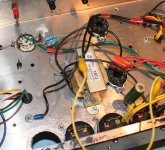
More progress. I wired up for the 6E5P more or less as Jef Larson's circuit (no diode in the g2 circuit yet).
I used a 50R pot for Rk and set it at what I thought was 50R but it turned out to be 47R and bypassed it with a Nichicon MUSE 220uF as this was what I had on hand.
I had to string together a bunch of resistors for the g2 supply, total 22k7 from B+ to the socket. I bypassed g2 to ground at the socket using a 47uF 160V cap.
I used a 1k stopper on g1 and wired it to the wiper of a 25k volume control.
Powered up... 😎
The cathode voltage settled out at around 1.57V, implying 33mA cathode current. The screen biassed up around 147V above ground, so around 145V above the cathode. It was drawing around 4mA and dissipating around 0.6W, well below the max rating of over 2W.
The anode was up at around 234V and by deduction the anode current was around 33 - 4 = 29mA. So the anode was dissipating less than 7W, comfortable given that Pa max is over 8W.
So far so good, for d.c. conditions at least.
This tube has a nice open structure, you can see the glow in all it's glory.
Attachments

Member
Joined 2009
Paid Member
ipad input, playing into a small full-range speaker (Mark Audio CHN70).
Very little volume, no bass and heavily distorted. Sounds like sh1t ! 😛
Very little volume, no bass and heavily distorted. Sounds like sh1t ! 😛
Member
Joined 2009
Paid Member
It works ! 6E5P in Tetrode
I was just about to get into bed and was halted by a flash of inspiration - I don't remember connecting both leads from the secondary of the output transformer ?!
I just went back down to the man-cave and checked. Yup, the '0V' tap of the output transformer was floating. I quickly soldered it to the amplifier ground / ground speaker terminal. Clearly, what I had been listening to was the signal leaking through the parasitic capacitance between the windings of the OPT and generating a small voltage with respect to ground.
All is well. The amplifier works! There is sound - plenty of volume, bass and all the rest. It's too early to say how good given the limitations of the iPad headphone output + MP3 but now I can go to bed.
🙂
Attachments

Last edited:
Hi Bigun,
I do also have a trioded 6E5P spud playing tunes. Well, not really a SPUD as I have two devices in parallel playing into a 2k5 OPT, but still a one stage amp.
another amp I have uses the 6E6P (which is similar to the 6E5P), but this one uses an input transformer for phase splitting, 6E6P connected as tetrode (well, curves look more like pentode, no nasty negative impedance region) into a 7k OPT.
Both are vey nice! My motivation to play with these came from the low THD figures measured by Mogliaa
THD benchmark | Bartola Valves
Member
Joined 2009
Paid Member
I do also have a trioded 6E5P spud playing tunes.
I first encountered the 6E5P reading stuff from Romy the Cat. In triode mode it looks superb. But I've seen very little in Tetrode. The data sheet is not too helpful either as it shows curves for modest plate voltages only.
Attached is the limited information from the data sheet that lead me to believe it can be quite linear in tetrode mode. But the tube I have doesn't seem to match with these curves - I'm getting less current than I would expect.
My operating point is with g1 at around 1.5V and g2 at around 145V. I should be seeing a lot more than the 30mA or so of plate current I measured. I have a few more of these tubes so I may try another one to see if it's the same.
Attachments

- Home
- Amplifiers
- Tubes / Valves
- Yukon Gold - a spud amp