Power Supply Rejection Ratio (PSRR) looks like is going to be really poor, so you may end up having considerable hum. Ii may be cheap, but it be worth the trouble?
It is a typical old AC coupled design. Build it if you have a PCB for it, otherwise choose another amp with a PCB that is known good. That amp is no simpler or easy to build than may other amps.
Old it may be but you may be surprised just how good it may sound. Look at the feedback factor.
It's ideal as a first project IMO, you have no worries about DC problems damaging speakers and the PSU will be simple.
It will work with just about any suitably rated transistors too...
Do you have the full construction details ? showing how to set up the bias etc and having T3 in thermal contact with the output transistors to keep it from thermal runaway.
It is very good...you gonna be happy with it.
Do not bother with modern and fashion circuits.... an enormous ammount of them sounds awfull.
You know when something sounds bad when you go tweaking tone controls and never feel satisfied..then you go to tweak your speakers, and then you replace speaker and speaker crossovers.. and then you tweak your home acoustics ..and continue not happy.... this happens when sound is no good.
When the amplifier is good you do not even need tone controls, all musics sounds good, nothing to tweak...it is easy that way.
regards,
Carlos
"Old it may be but you may be surprised just how good it may sound. Look at the feedback factor.
It's ideal as a first project IMO, you have no worries about DC problems damaging speakers and the PSU will be simple.
It will work with just about any suitably rated transistors too...
Do you have the full construction details ? showing how to set up the bias etc and having T3 in thermal contact with the output transistors to keep it from thermal runaway. "
Solid Advice.
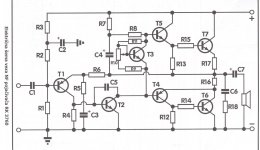
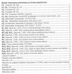
Dear frends, T3 is bias control, this transistor shold be to put in to heatsink with outputs transistors,think in same place(heatsink, because good termal stabilty) .
About hum,yes that is probably problems,but with BC550,and metal films resistors,maybe hum to be low.
This is kit,and I get(buy) a PCB with parts and manual instruction,my job is only conclude.
This kit is in circulation but ten years.
I wanted to build later in bridge mode,but speaker shold be 8 ohm's,
Sounds like a good project for you then, although I think 1/2 watt for R16 and R17 is far too small. Maybe it is a mistake and it should say 2W.
Last edited:
This circuit is one of my prefer topology for Class AB mode (20-30mA idle current through the output devices). If there are 10-15 mA idle current for T1 and 30 - 50mA for T2, so as additional jFET input buffer and high quality capacitors/transformers, then such an amplifier is very hard to beat (except nessecary concepts with pure class A in the output).Please, tell me your opinion,about this old schematics.
I know that this schematics is old,low hi-fi,but easy to building, and cheaping.
Yours experience?
There are also some commercial amplifiers, that have inside this topology, e. g. the no longer exist U.K. brand "Nytech", model No CA202 (CA-202), have a look to http://images.deep-resonance.net/image/85.jpg
http://i36.tinypic.com/2chxelx.jpg
and the pdf file:
Attachments
Most engineers from audio developing claims, that the capacitor between output and loudspeaker terminal is a disadvantage for best sonic quality, because one loss the DC coupled character, i. e. lower damping factor in the aera of the low roll off by frequency response. But I claim nevertheless, it is an advantage.you have no worries about DC problems damaging speakers
First, I don't need a relais contact in series for the aim of DC protection and second, I can optimize the value of capacitance to my presently high pass function of the relevant loudspeaker model, especially by closed boxes.
Very important is of course highest quality capacitor versions like this one e. g.:
http://www.ftcap.de/seiten/en/products/electrolytic/reihen/Reihe_G_.php
http://www.ftcap.de/downloads/elektrolyt/datenblaetter_2009/GW2009.PDF
and sufficient reserve (minimum 30 - 50%) by the choice of the max. DC voltage.
In general, versions "special made for audio" should be - in my opinion - avoided, especially by a very low product of capacity x volume.
Instead of this one always ensure that the capacitors are suitable for professional applications. e. g. industry, military aeronautics and space (large screw terminals in most cases). Then the quality is also perfect for audio.
The same goes also for those one in power supply and for the boostrap function
Last edited:
Output cap or filter cap - that is the question......
Even if you direct couple, and use a bipolar power supply, you still have speaker earth return currents travelling through the filter caps.
Ergo, it is not too important if you use direct coupling or not. A large cap will be in the speaker current path regardless.
Hugh
Even if you direct couple, and use a bipolar power supply, you still have speaker earth return currents travelling through the filter caps.
Ergo, it is not too important if you use direct coupling or not. A large cap will be in the speaker current path regardless.
Hugh
About hum,yes that is probably problems,but with BC550,and metal films resistors,maybe hum to be low.
Hum should not be a problem if you correctly wire the amp(s) paying regard to grounding etc.
The quiescent current is low and will not load the PSU much (increasing ripple) so I would not worry over that.
Output cap or filter cap - that is the question......
Even if you direct couple, and use a bipolar power supply, you still have speaker earth return currents travelling through the filter caps.
Ergo, it is not too important if you use direct coupling or not. A large cap will be in the speaker current path regardless.
Hugh
Hi Hugh,
I wouldn't perhaps quite put it like that 🙂
I am thinking of the way D Self explained this, that the caps (PSU) are "outside" the influence of the amp. The output of the amp is determined more by correct feedback and ground returns etc. What goes on at the PSU is immaterial as such.
Different sort of interpretation I guess, but a valid one.
I've lost count of the number of amps I've built using this (or similar in geranium).
When I was at uni. in the early '70s, everyone was building these amps.
The uni. discos ran on them!
Andy
Edit : The output resistors should definitely be at least 2w wirewound .
When I was at uni. in the early '70s, everyone was building these amps.
The uni. discos ran on them!
Andy
Edit : The output resistors should definitely be at least 2w wirewound .
Last edited:
Mooly,
That`s rubbish, like many things he said. Everything is inside the influence of the amp. Be very careful with what you use in any location.I am thinking of the way D Self explained this, that the caps (PSU) are "outside" the influence of the amp. The output of the amp is determined more by correct feedback and ground returns etc. What goes on at the PSU is immaterial as such.
Mooly,
That`s rubbish, like many things he said. Everything is inside the influence of the amp. Be very careful with what you use in any location.
consider a conventional DC coupled amp and split supply, but instead of a 50/60hz mains supply and transformer and accompanying large reservoir caps you have a suitably rated SMPS operating at say 50khz plus with small reservoir caps.
Are you saying the performance of the amp would be limited at low frequencies because of the small reservoir caps, due to the fact the speaker current has to pass through them ? I think not 🙂
Mooly,
Absolutely, as they are in series with the load, just like C7.Are you saying the performance of the amp would be limited at low frequencies because of the small reservoir caps
Sorry... it just doesn't work like that.
What about if the amp has a response to DC and output's 10 volts DC across 10 ohms (for example) so that 1 amp flows. It's a valid output signal. Where does the load current go ? Through the caps ?
Are you saying that 1 amp DC flows through the reservoir caps ?
What about if the amp has a response to DC and output's 10 volts DC across 10 ohms (for example) so that 1 amp flows. It's a valid output signal. Where does the load current go ? Through the caps ?
Are you saying that 1 amp DC flows through the reservoir caps ?
Mooly,
capacitors cannot pass DC current.
The signal current flows through the supply capacitor and the load back to the amplifier, introducing various distortions.
So, power supply capacitors act as an energy reservoir, a filter component, signal wise being in series with the load. Smoothing occurs according to the formula:
Ripple voltage = load current x power supply frequency / filter capacitor
Please observe the current / capacitor relationship. The capacitor bank in your amp is ridiculously small.
Attachments
- Status
- Not open for further replies.
- Home
- Amplifiers
- Solid State
- Your opinion about this schematics?