I would imagine that 2 amps built the same drift similar amounts so the cap isn't needed.
But I do agree Mooly that for the "gains" bridging is not worth the extra hassle for this guy.
But I do agree Mooly that for the "gains" bridging is not worth the extra hassle for this guy.
don't mean to butt in here rather rudely, but I think Mooly and another user did explain why: becuase of instability with the midpoint voltage, and the need for a phase inverter (mind you a transistor with taps on emitter and collectro would work fine I suppose).
But mainly for this reason, which is my own:
This is a circuit that was designed decades ago, when bridging wasn't even a word in audio. It would be counter-intuitive to apply modern-day techniques to an old design which will only show more its shortcomings in bridged mode. It will not retain its essence. At least that's what I think. I have an amplifier that is a copy of an EICO Cortina 3070, just like the schematic (very close) and can tell you that the midpoint voltage is not only subject to instability, but has the "thump" when you turn it on...
If you want more power, why not then take another design, like the more common PNP-NPN push pull circuits?
Or simply raise the supply voltage...
Why do you say the circuit is unsuitable for bridge?
but has the "thump" when you turn it on...
This problem exists with today's modern amplifier also.
This problem is solved using individual components.
I want to say that there are seeds that will solve it
I know that will need me to phase inverter for bridge amplifier.
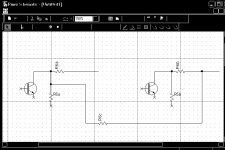
I send you a scheme very simple inverter.
Edit my sheme with the differential pair of transistors requires a good knowledge constructors.I do not have to.
If I had the offset of the 2-3V, I know that it is more complex and spam.
Then I have a big problem to make the bridge amplifier
I hope so that I don't have that big ofset.
I think that dissipation of offset voltage to be spend on emiters resistors on output transistors?Am I right?
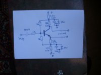
Can you tell me whether this amplifier can really give 25W?
The voltage of 30V, I think I can not get 25W?
Attachments

Hi Pigy,
30 Volts supply will give you around 26 volts peak to peak across the load (transistor losses and all) which is around 10 watts rms into 8 ohm and 20 watts into 4 ohm
30 Volts supply will give you around 26 volts peak to peak across the load (transistor losses and all) which is around 10 watts rms into 8 ohm and 20 watts into 4 ohm
This problem exists with today's modern amplifier also.
This problem is solved using individual components.
I want to say that there are seeds that will solve it
I know that will need me to phase inverter for bridge amplifier.
I send you a scheme very simple inverter.
Edit my sheme with the differential pair of transistors requires a good knowledge constructors.I do not have to.
If I had the offset of the 2-3V, I know that it is more complex and spam.
Then I have a big problem to make the bridge amplifier
I hope so that I don't have that big ofset.
I think that dissipation of offset voltage to be spend on emiters resistors on output transistors?Am I right?
Can you tell me whether this amplifier can really give 25W?
The voltage of 30V, I think I can not get 25W?
Attachments
Hi Pigy,
I think you have to decide what you want to do 🙂
I still say the design is not suited to bridge operation for all the reasons outlined.
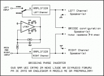
If you go ahead anyway then the IC phase splitter is best (you need a split supply) and you must AC couple the speaker.
I think you have to decide what you want to do 🙂
I still say the design is not suited to bridge operation for all the reasons outlined.
If you go ahead anyway then the IC phase splitter is best (you need a split supply) and you must AC couple the speaker.
Some years ago I find on the web a German diy project, that have the same topology. Unfortunately this article is deleted. Because I have store this websites, I have make a pdf file (see botton). The same author has descript a possible of a bridged version about this topology - but unfortunately this article I haven't. Both article was release in the no longer available German diy magazine "ELRAD" (not "elector") between 1985 and 1990 - as I know.
You can ask Mr. Gerhard Haas about this article, title "Brücken-Teufel" (bridge devil) - Go to the weblink
EXPERIENCE electronics - Contact
to send an e-mail about this -
because about EXPERIENCE electronics - HiFi-Amplifiers 'Classic'-Series
this information presently not available
Many thanks for mentioning these amps and for the links - I have made one of these "black devils" way back in 1986, I think, but it had such a good sound that some studio people never gave it back to me. Why did that design not create more attention? Even in those days simple design with output caps were somehow suspect...
Gerhard Haas published another article with some modifications to the original circuit, do you have this informations? (I have only the orginal ELRAD mags with the basic article. - ELRAD was btw also the first magazine which published John Lindsey Hood in german)
I would not use that method on this amp as the different gains and feedback resistors will cause different offsets.
There is a balanced line output project on my website which would be exactly what you need to produce identical but phase reversed signals that will happily drive the amp.
There is a balanced line output project on my website which would be exactly what you need to produce identical but phase reversed signals that will happily drive the amp.
I would not use that method on this amp as the different gains and feedback resistors will cause different offsets.
R5 is capacitively coupled, the DC gain is 1. How bad could it be with just a little resistor selection? 50 mV?
There is also the issue that the stability and high frequency response of the amps will be different due to vastly different feedback factors.
Not so fast - the noise gain is still set by 1+(R6/R5), even on the unity gain inverting channel. They did this on the old BGW 500 (and the original CS800 and every other clone out there) and it worked just fine.
Member
Joined 2009
Paid Member
funny how old questions resurface in different threads - I'm referring to the discussion about output capacitors. I think it's wrong that some commentaries on the web refer to output capacitors as bad. I'm 100% with Hugh and Lumba on this one - the power supply is in the path of current that flows through the speaker. The a.c. current flow through the speaker flows through the output stage of the amplifier and also the power supply - through the filter caps.
The only real question for me is where the feedback is taken from. If the output capacitor is outside the nfb loop then the behaviour is different than if it is put inside the nfb loop (with attendant problems).
The only real question for me is where the feedback is taken from. If the output capacitor is outside the nfb loop then the behaviour is different than if it is put inside the nfb loop (with attendant problems).
Please,tell me what are the disadvantages of amplifier in bridge mode?
Do you then this amplifier have more distortion?
Generally, the amplifiers in bridge mode have a poor performance when a single(standard mode)?
Thank you!🙂
Do you then this amplifier have more distortion?
Generally, the amplifiers in bridge mode have a poor performance when a single(standard mode)?
Thank you!🙂
A single amp that runs on 2X volts will generally have better perfromance than a bridge that runs on X volts. Lower distortion, higher output swing as a percentage of supply voltage, lower parts count. But perhaps a bridge amp may be worthwhile if you're trying to get the most watts out of what you may already have. Say, a 30 volt high current transformer that may or may not have a center tap, a bunch of big 50V soup can caps, 100 volt power transistors...

The circuit is similar and will present the same issues.
Just build the first one in the kit, bridge will get you just 3dB more output, you won't notice it. It's not worth the hassle and complication, forget about bridge.
Just build the first one in the kit, bridge will get you just 3dB more output, you won't notice it. It's not worth the hassle and complication, forget about bridge.
Frend, could you help me when and if I bild this amplifier in bridge mode.
I build first in the kit,with 2N3055( my first shematic),than later I wont build with AD150.
If I am satisfied with the sound than I make as bridge mode(AD150- second shematic).
Can I count on your help?
I like to do in bridge mode ,bacause in 8 ohms amp give me only 10-12W(this is too small power),and I like to build with Germanium transistor.
Thanks for help!
Last edited:
The second is curiosity value only... germanium devices...
Build the first one as per the circuit. You will be amazed at how good it sounds, and from a kit you have a better chance of success if you take it slowly and check everything along the way.
Forget bridging it too.
Why do you want to use Germanium... ? It would be so prone to problems, possible unreliability and thermal issues. Anything warmer than a cold cup of coffee and you would be in trouble 🙂
- Status
- Not open for further replies.
- Home
- Amplifiers
- Solid State
- Your opinion about this schematics?