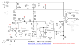
I only recently discovered this DC converter and I have one on the way. I wish to thank the members of this sight for the work already done. I have been working on the schematic and I have attached my version. I believe it to be more accurate but by all means not perfect nor error free.
Bob

Bob
Hi Bob,
If you want to work on the module in LTSpice first, I have a UC3845 model available on my GIThub repository.
https://github.com/stefaweb/audio-psu/tree/main/HV-MODULE-UC3845-1.0
The YH11068A module cannot be used with tubes. It has several serious issues, some of which make it even dangerous (overvoltage sometimes non-functional).
Stef.
Bob, pcb version may have changed over the years. As such, if you have noticed differences between your schematic and others then perhaps best to identify the differences, rather than just post another schematic. I quickly noted your schematic doesn't show an input fuse - which may be related to later pcb version, or how your pcb was populated.
Stef, I'm not sure how you conclude that the module 'cannot' be used with tubes ? Perhaps better to identify the serious issues you have noted, and elaborate on why overvoltage protection may be 'sometimes' non-functional.
Ciao, Tim
Stef, I'm not sure how you conclude that the module 'cannot' be used with tubes ? Perhaps better to identify the serious issues you have noted, and elaborate on why overvoltage protection may be 'sometimes' non-functional.
Ciao, Tim
I spent a lot of time testing the YH11068A module (my tests are only available on a French forum, sorry).
I also ran endurance tests with the module at 350V/60mA. The out-of-the-box module burned out after an hour. The modified module (new branded US3M diodes, new HV output capacitors, new 0R025 sensing resistor) burned out after 4 hours.
So, I'm currently making one of my own. 😉
Stef.
- It doesn't exceed 15/17W under normal use. Above that, it gets too hot and has thermal drift that increases until the module burns out (the input consumption increases until it burns out).
- It has a large thermal drift between cold and hot (over 5V).
- Out-of-the-box, the module's ripple is poor (between 5V and 10V for 350V).
- When starting module with a load (for example, 10K at 350V), it sends 650V to the output for 1 second.
- The transformer's windings are too close together, making its insulation inadequate.
- The current-sensing resistor is a 0R010/0R008. It's also a simple metal plate, not a real resistor.
- It doesn't work at 24V with a heavy load (you need to replace the sensing resistor with a 0R025). The overcurrent keeps tripping.
- It doesn't have a soft start. As a result, when you start the module with a heavy load, it draws more than 3A or 4A on the 24V input for a few milliseconds. The power supply goes into protection mode (if it has one).
- The PCB is poorly designed. The capacitor of the RC current filter isn't close to pin 3, and the oscillator RC parts aren't close to pin 4 of the UC3843.
- The ground plane is not good, especially around the current-sense resistor and the UC3843.
I also ran endurance tests with the module at 350V/60mA. The out-of-the-box module burned out after an hour. The modified module (new branded US3M diodes, new HV output capacitors, new 0R025 sensing resistor) burned out after 4 hours.
So, I'm currently making one of my own. 😉
Stef.
Thank you Stef for the information. I now have the PCB in my possession and plan to experiment with it. Overvoltage conditions should be easily remedied. I suspect that other problems may be caused by the wide output voltage range. I believe modifications can be made to make it more stable with a limited range.
Hi Bob,
Good luck. Keep us posted on your tests. I should start testing my prototype in early May when I get back from vacation. On the prototype I have, the UC3845 part works, but I haven't bought the Wurth transformer yet.
In the meantime, I'm testing the circuit in LTSpice to try to refine the current circuit.
Stef.
ps: You can find more UC38xx models here: https://ltwiki.org/files/adventures_with_analog/my_model_files/
Attachments

Given I started this thread, I'd just like to comment that over the last 9 years many cheap dc/dc converter modules of various types and styles have become available, and can be very useful to try out for a multitude of reasons. For my diy audio needs I tend to now use an inverter module and add my own secondary side rectification and filtering, with no need for secondary side feedback (as the stiffness of the secondary side supply is typically sufficient, and a titch of sag can be a benefit), and generally just relying on primary side UVLO to indicate a problem has arisen.
Hello,
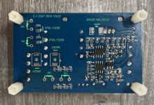
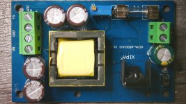
There is another DC-DC module that works better than the yellow one. I call it "the blue module".
XIPA-650CHVC
https://www.lingao.site/laxipa/
It can be found at several retailers on Aliexpress. It is manufactured by the company linked above.
It holds 20/25W (tested at 350V/70mA) and has survived endurance tests (10 hours of continuous operation at 350V/60mA).
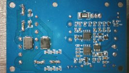
The transformer is not the same as the yellow module. The PCB is better made and the components are of slightly better quality. Since it doesn't oscillate like the yellow module, the MOSFET and transformer don't get very hot. However, for some incomprehensible reason, they have scratched most of the component references, but it seems to be a copy of the yellow module.
It basically requires some modifications to improve it. Once done, we have correct specifications.
Result of one of my tests:
Positive output: +350V
Negative output: -125V
Consumption at 350V: 61mA
Consumption at 24V input: 1A
Ripple on the positive output on the load: 210mV (310mV, 4V pk-pk on the scope at the power supply output)
Out-of-the-box in the positive output only version, the ripple is 10V at 350V, which is not great.
Here are some photos.
Stef.
There is another DC-DC module that works better than the yellow one. I call it "the blue module".
XIPA-650CHVC
https://www.lingao.site/laxipa/
It can be found at several retailers on Aliexpress. It is manufactured by the company linked above.
It holds 20/25W (tested at 350V/70mA) and has survived endurance tests (10 hours of continuous operation at 350V/60mA).
The transformer is not the same as the yellow module. The PCB is better made and the components are of slightly better quality. Since it doesn't oscillate like the yellow module, the MOSFET and transformer don't get very hot. However, for some incomprehensible reason, they have scratched most of the component references, but it seems to be a copy of the yellow module.
It basically requires some modifications to improve it. Once done, we have correct specifications.
Result of one of my tests:
Positive output: +350V
Negative output: -125V
Consumption at 350V: 61mA
Consumption at 24V input: 1A
Ripple on the positive output on the load: 210mV (310mV, 4V pk-pk on the scope at the power supply output)
Out-of-the-box in the positive output only version, the ripple is 10V at 350V, which is not great.
Here are some photos.
Stef.
Attachments
I only recently discovered this DC converter and I have one on the way. I wish to thank the members of this sight for the work already done. I have been working on the schematic and I have attached my version. I believe it to be more accurate but by all means not perfect nor error free.
BobView attachment 1451323
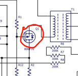
Wrong. Should be a N-Channel.
The STP80NF70 is also NRND.
Stef.
Attachments
Hello,
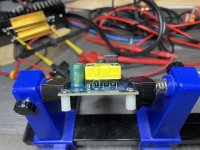
I started testing my module. 👍
At +350V with 60mA load, it seems stable with a ripple of 240mV (24mV with a load of 1mA). +1V offset between the cold and hot module (12/hour).
I have a lot of testing to do to optimize it and need test the version with the LM358A (positive feedback).
Regards,
Stef.
I started testing my module. 👍
At +350V with 60mA load, it seems stable with a ripple of 240mV (24mV with a load of 1mA). +1V offset between the cold and hot module (12/hour).
I have a lot of testing to do to optimize it and need test the version with the LM358A (positive feedback).
Regards,
Stef.
Attachments

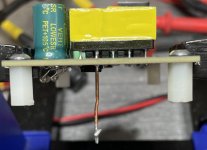
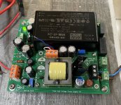
The HV board with the optional dedicated PSU board (24V 45W + 30KHz external filter + 12V to connect accessories).
Test at +350V with 60mA of load. Ripple = 60mV.
Stef.
Test at +350V with 60mA of load. Ripple = 60mV.
Stef.
Attachments
Last edited:
- Home
- Amplifiers
- Power Supplies
- YH11068A 10-32V to 45-390V dc/dc - guess the control ICs