Hello,
I am seeking to understand what the effects are of a higher Yfs (or gfs) parameter on the sound of a Pass amplifier, specifically the AJ. For example, the typical IRFP9240/240 are in the range of 4. Then consider an FQA24N60 with a yfs/gfs of 22. What is the effect of this difference in terms of operating parameters and more importantly noticeable sound quality? I guess the last question would be for anyone that's actually tried such a high gfs device and compared it to the sound of the part selected by NP. I imagine higher gfs devices were available when he designed the AJ, but evidently he believed that the 9240/240 was the right part (and maybe all other key parameters being approximately the same)
Thanks for your feedback.
This thread may be of interest: https://www.diyaudio.com/community/threads/power-mosfet-choices.19295/
For example, the typical IRFP9240/240 are in the range of 4. Then consider an FQA24N60 with a yfs/gfs of 22.
Its important to understand that Yfs is a very strong function of the drain current in the device. Hence for comparing apples with apples, the Yfs should be compared at the same current. Often that's difficult as MOSFET datasheets only cite the Yfs at a single, fairly arbitrary current.

Yes...and most do not put anything at all for gfs, and likely for that very reason.Its important to understand that Yfs is a very strong function of the drain current in the device. Hence for comparing apples with apples, the Yfs should be compared at the same current. Often that's difficult as MOSFET datasheets only cite the Yfs at a single, fairly arbitrary current.
And to further clarify - if transconductance is a function of the bias point, thenin terms of the AJ's bias at (0.40V/0.47ohms) = 850mA, where does the rubber meet the road? Or the gain hit the rails? 😎
But again, my question still stands: in the AJ, has anyone actually tried a higher gfs device (with other parameters similar) and if so, what differences did they think were audible? (maybe this is a post for the AJ forum!)
And thanks @dennishui for posting that link. I read through it and although NP posted his thoughts, it still leaves me wondering what those audible qualitative differences might be...
Yes...and most do not put anything at all for gfs, and likely for that very reason.
I suspect the reason for the paucity of data on Yfs/gfs is that FETs (more particularly VFETs) are generally designed for and used in switching applications where its not relevant. The FETs which are explicitly designed for linear applications often provide an Id/Yfs graph. For example 2SK1530 : http://www.cordellaudio.com/book/datasheets/2SK1530.pdf
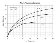
Not an answer to OP's actual question about the difference in sound, but you can guesstimate the transconductance from the transfer characteristics, which is practically always provided. In this particular case, both IRFP240 and FQA24N60 have about 2S around 1A at 25°C...
in general - if there is increase of xconductance, result is higher gain of whole circuit, be it in voltage domain (think - open loop gain) or just current domain ( in case of source follower configuration of OS) ..... all in all - lesser THD
now, is it going to end in better sound, that depends of actual ears- brain combo, in other words - personal preferences for THD Spectra and also THD levels
as shown by Papa myriad times here (and by some other Fellows around) - non-existent THD is Holly Grail imposed by FiFi periodics, of Yore and present, while real life is showing that things aren't so uniform and simple and easy
Interesting. So when you look at the transfer characteristics at 1A (approx the bias current) to derive the gfs of 2S, is it a matter of dividing the change in Id/Vgs? What Vgs, Vds values did you use?Not an answer to OP's actual question about the difference in sound, but you can guesstimate the transconductance from the transfer characteristics, which is practically always provided. In this particular case, both IRFP240 and FQA24N60 have about 2S around 1A at 25°C...
Those are large variances given the published gfs of the 244 is 6.8S, and the FQA part is 22! I also realize the transfer curve is different on both.
Siemens is just Ampere per Volt. The FQA chart shows 0.1A at ~4.3V and 2A at ~5.3V, so a 1V change of Vgs gives you a change of 1.9A in Id. Hence, ~2S. For the IRF, we have 0.1A at ~4V and 2A at close to 5V, so ~2S again. Of course, because the Id is on a log axis, the actual gfs would be a little higher, but just to quickly compare these 2 parts this kind of guesstimate should be good enough. RE the wildly different gfs figures in the data sheets - please be careful to compare "apples to apples" as already mentioned above: The IRF's 6.9S (at 12A) is the MIN value while the FQA's 22.5S (at 11.8A) is the TYP value. The charts usually show the typical values, and in this case they're even both conveniently defined at the same Vds of 50V, so it should be a fair comparison.
Thanks for the explanation. Again - I do not want to question the wisdom of NP's choices in parts, nor am I looking to drill it down to technical merit. It would be good to know "what differences I would hear", and further, would those differences be enough to warrant changing out the parts? I have a pair of Aleph J's running bi-amp. Does it sound great? Yes. Could it sound better? Maybe, and the reason for my post.
Thanks for your feedback. If and when I change them in at least one amp I'll post my thoughts/feedback.
Thanks for your feedback. If and when I change them in at least one amp I'll post my thoughts/feedback.
As a point - different manufacturers put a lot more effort into datasheets. Looking at ST's, they never have transfer characteristics under 1A, so it's hard to tell as the curves are too flat. But look at the attached graph of a IXTH20N65X2 from IXYS. They actually insert a graph of gfs vs temperature and take all the work out of it. Too bad they can't all do this!Siemens is just Ampere per Volt. The FQA chart shows 0.1A at ~4.3V and 2A at ~5.3V, so a 1V change of Vgs gives you a change of 1.9A in Id. Hence, ~2S. For the IRF, we have 0.1A at ~4V and 2A at close to 5V, so ~2S again. Of course, because the Id is on a log axis, the actual gfs would be a little higher, but just to quickly compare these 2 parts this kind of guesstimate should be good enough. RE the wildly different gfs figures in the data sheets - please be careful to compare "apples to apples" as already mentioned above: The IRF's 6.9S (at 12A) is the MIN value while the FQA's 22.5S (at 11.8A) is the TYP value. The charts usually show the typical values, and in this case they're even both conveniently defined at the same Vds of 50V, so it should be a fair comparison.
Attachments
NP keeps it simple: Keep it in class A with higher bias = lowers the distortion. Tons of proven IRFPs in his parts drawer...
hehe, I'm only interested in the actual used "tons", the others are dead weight. And as for bias, yes...nice if your heat sinks can blow it off. I may adjust higher and run a low speed fan in the vicinity just to move a bit of air. I did design a microcontroller based soft-start board and active L-R temperature monitoring which is a big plus. But all for not if it hits the heat sink limit of 55C in half the time. So it's finding the middle ground that counts.
Actually, this article from NP has a great deal of very useful information on transconductance, calculation and measurement. Seek...find. I did it. 😳
https://www.firstwatt.com/pdf/art_mos_test.pdf
https://www.firstwatt.com/pdf/art_mos_test.pdf
Last edited:
I think the general article consensus (other than in-depth discussion of test methods) is that higher Id can make it sound better. I may try this in the next day or so to see what, if any audible subtleties there are. I'll bump up to 1A from 850mA. If it's audible I will connect up the test gear to see if it's something measurable. I have an HP 8903B audio analyzer, but have resisted connecting it up because in the past as it can been a bit misleading. You can measure something that says it should be good, but then a listen reveals...maybe so-so. Now I am curious what I will measure.
- Home
- Amplifiers
- Pass Labs
- Yfs, Transconductance of MOSFETS