After a long period of inactivity, I've decided to take another look at my DAC. The TDA1387 board I'm using doesn't have any onboard supply regulation, so that seemed like a good place to start. So I added a couple of off-board 7805 regulators, one for the SPDIF receiver and one for the TDA1387 array, and bypassed the on-board RC networks on the supply rails. The results were, I suppose, pretty predictable: reduced audible distortion, increased detail and improved definition of instrument timbre.
All in all, pretty predictable results, I imagine. So now I'm think about implementing a shunt supply for the TDA1387 array. I've been thinking about the one Peter Daniel published a few years ago, but I'm open to suggestions.
All in all, pretty predictable results, I imagine. So now I'm think about implementing a shunt supply for the TDA1387 array. I've been thinking about the one Peter Daniel published a few years ago, but I'm open to suggestions.
More updates. The 7805s have been replaced by a SSLV1.3 UltraBiB (thanks Salas!) which subjectively provides significantly more information across the spectrum without any added harshness or edginess.
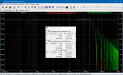
With that new baseline, I've reworked the sinc droop correction filter. It's now a simpler, underdamped 2nd order Butterworth, which gives a sinc droop corrected response that is down less than 1dB at 16kHz (the red trace in the attached plot). The green trace shows the uncorrected output. Full scale output is also now closer to 1 VRMS.
With that new baseline, I've reworked the sinc droop correction filter. It's now a simpler, underdamped 2nd order Butterworth, which gives a sinc droop corrected response that is down less than 1dB at 16kHz (the red trace in the attached plot). The green trace shows the uncorrected output. Full scale output is also now closer to 1 VRMS.
Attachments
As the TDA1387 has unipolar current output there is a static current (almost 600uA) coming out at digital zero. This current has noise (at the very least in an ideal current source it has shot noise and we can assume its less than ideal) which gets turned into voltage by the I/V resistor. So there's a noise source effectively in series with the I/V resistor when its biassed with a static current. If the static current is 'bled' away with an external CCS then that noise source can be eliminated.
The noise can be less than full shot noise (sqrt(2q I Delta f)) when the sources are degenerated, but there will definitely be noise on the 600 uA.
When you have 600 uA plus some small variation and you subtract 600 uA, you are still left with the small variation. That is, I don't believe subtracting the DC current will reduce the DAC output current noise. It will reduce noise due to random variations of the current-to-voltage conversion resistor, that is, resistor 1/f noise, but you can keep that very small anyway by using metal film or wirewound resistors.
I agree with all of that. I guess my explanation wasn't clear enough - I was comparing an I/V resistor in series with a voltage reference and driven push/pull against an I/V resistor to 0V driven single-ended.
A spice noise simulation doesn't indicate any issues with noise from the I-V resistor. I'm using a Dale RN55 in that location, so I'm not worried about noise there. I'm also not terribly worried about the reflected images above 22kHz, though I'll probably investigate steeper anti-aliasing filters again at some point. To date the biggest sound quality improvements have been due to implementing good power supplies on the TDA1387 and on the output CF. Rather than noise, I'm more concerned with the added distortion from using so much of the chips' output compliance. I'm contemplating a triode based I-V converter to reduce the voltage swing at the TDA1387 output pins and I think I have a workable concept that will work with the TDA1387 bias current.
I've also noticed my LTSpice sims for noise don't show the noise resulting from current shot noise through a resistor. I just assumed the simulator wasn't missing that as I can't see why it wouldn't be an issue from the physics. But perhaps its me that's missing something vital.
As regards images, to my ears a less-well filtered NOS DAC produces an out-of-focus stereo image compared to one with steeper filtering. I concur that low hanging fruit is power supply quality for the DAC and following circuits. I'm much less concerned about distortion than about noise - it seems to me the reason power supplies are so crucial to the subjective result is because they eventually contribute noise (via circuit PSRR, the DAC's PSRR is relatively low, 30dB). I prefer not to use all the DAC's output compliance though.
As regards images, to my ears a less-well filtered NOS DAC produces an out-of-focus stereo image compared to one with steeper filtering. I concur that low hanging fruit is power supply quality for the DAC and following circuits. I'm much less concerned about distortion than about noise - it seems to me the reason power supplies are so crucial to the subjective result is because they eventually contribute noise (via circuit PSRR, the DAC's PSRR is relatively low, 30dB). I prefer not to use all the DAC's output compliance though.
@abraxalito How do you model the DAC and how do you model the resistor? When you use an ideal LTSpice current source and resistor, you get no noise whatsoever from the current source and only thermal noise from the resistor.
I guess you would need to include a .model statement for the resistor to model its 1/f noise, although I'm not sure about that. Maybe there is some parameter you can turn on without .model.
A practical current source implementation can produce less as well as more than full shot noise. Extreme example, a well-filtered 6 kV power supply with a series of wirewound resistors with a total resistance of 10 Mohm would be a pretty good 600 uA current source: 10 Mohm of differential resistance and only 40.71 fA/sqrt(Hz) of noise. Of course that's not a likely implementation of the current source inside the DAC chip, but the point is that you can't model the DAC current noise without knowing how much it is, which depends on the internal circuit.
It seems I've been operating on an understanding of shot noise in a resistor which hasn't taken account of what Wikipedia refers to as the interaction of electrons as a result of the Coulomb force. It says that in wires and metal film resistors this interaction cancels out shot noise so there's no resulting extra voltage noise as a result of the current flowing, beyond the resistor's thermal noise. I'd not come across this before so my bad.
However Wikipedia's article on shot noise which I've been relying on does also say that when the noise current is passed through a resistor the shot noise generates a noise voltage so this does rather seem to contradict what it says only a few paragraphs above.
@MarcelvdG what formula did you use to determine the current noise from your 6kV-fed current source? I've been using SQRT(2*q*I*deltaf) for shot noise which doesn't agree with your 40fA figure on 600uA (about 14pA/rtHz).
What they taught me at university is that you only get shot noise when the charge carriers cross a potential barrier, and that that happens in a semiconductor junction, but not in a resistor. Resistors have thermal noise, a.k.a. Johnson noise, instead. (There are situations where the distinction between thermal and shot noise sort of disappears, though; when you have a MOSFET in weak inversion biased at zero drain-source voltage, you can describe its noise as shot noise of a hypothetical forward and a hypothetical backward current, but also as thermal noise of its drain-source resistance. The result is exactly the same.)
On top of that, there are all sorts of 1/f noise. In a resistor, those manifest themselves as random variations of the resistance. 1/f noise in wirewound resistors is extremely small, hence my preference for making the hypothetical 10 MΩ with wirewound resistors. Metal film and thin film resistors are also pretty good, though not as good as wirewound resistors.
Thermal noise can be described with a noise voltage source √(4 k T R Δf) in series with the resistor, or with a current source √((4 k T/R) Δf) in parallel with the resistor, where k is Boltzmann's constant, 1.380649 * 10-23 J/K. The latter equation boils down to 40.71 fA/√Hz for 10 MΩ at the default SPICE temperature of 300.15 K.
It's actually a low-frequency asymptote. When you make microwave circuits at cryogenic temperatures, you have to account for the Planck factor that reduces the noise density of thermal noise.
Last edited:
Ah thanks, so seems I've been too pessimistic in taking shot noise to apply to all currents no matter where they're flowing. Which was the impression I got from reading Wikipedia. From that article it seemed to me that shot noise was inherent due to the nature of current being discrete electrons, a kind of quantization noise baked into all currents everywhere.
So the upshot of this is then, assuming a very good (wirewound) resistor the amount of current flowing through it has no impact on the noise voltage across it, that's always and only determined by the thermal noise equation. There will be some noise associated with the current source generating that current to be taken account of though but that's going to depend on how the current was created, not on the SQRT(2*q*I*deltaf) equation.
That's helpful, I can go back to trusting LTSpice's noise simulations now 🙂
There can be excess noise and or distortion caused by current flowing through a resistor's end-cap-to-resistive-element connection.
IIRC a tidbit from 'Art of Electronics.'
IIRC a tidbit from 'Art of Electronics.'
Agreed.it seems to me the reason power supplies are so crucial to the subjective result is because they eventually contribute noise (via circuit PSRR, the DAC's PSRR is relatively low, 30dB).
By loading the DAC outputs with resistance to ground, the generated output voltage will always hover at the low end of the compliance range, with negative peaks nearing 0V. With the added reactance of the LP filter, the output voltage peaks will exceed the envelope suggested by a pure resistive load. In this instance I have seen the negative peaks go below 0V using contrived signals (sox generated white noise @0db). When the signal returns above ground it takes a few cycles for the DAC to recover. I've not observed that occurring on an actual music signal, though. However, just to be safe, I now add small current sources between the 5V rail and the DAC outputs to bring the zero signal output up to 1.8V, centering it in the compliance range.I prefer not to use all the DAC's output compliance though.
This looks like super musical! What is the maximum RMS voltage output under normal load in this implementation?
Thanks for taking a peek.
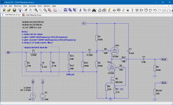
I've changed the circuit a bit since the last schematic was posted.
The cathode follower now incorporates an improved biasing network. Distortion of the cathode follower into a 100 kohm load is acceptably low at about -95 dB for H2 and more that -100dB for H3 and higher at full output. JJ and EH tubes both perform nicely.
The RLC network has been removed due to some concern on my part that it was having a negative affect on the sound. So the frequency response now exhibits the classic NOS sinc droop and, as a result, sounds a bit dark or rolled off. This issue is not yet resolved for me.
I did lower the value of the IV resistor from 680R to 560R to use somewhat less of the TDA1387's output compliance, as suggested by Abraxalito. With that in place, the output is nominally 0.78 Vrms, which is not an issue for me as I am using a preamp with gain.

- Home
- Source & Line
- Digital Line Level
- Yet another TDA1387 NOS DAC with tube output