There was actually a real commercial design done the DSelf way and it was also one of the best at its time.If a fet input op-amp is used there's no real problem with the resistor noise in inverting topology...Douglas Self discusses at length the use of MUX in his small signal book. The best implementation thd wise uses one 4066 per channel in conjunction with an inverting opamp. You can get most of the discussion in the preview of the book on google books: Small- Signal Audio Design - Douglas Self - Google Livres (search 4066 and then scroll down to fig 16.17)
It goes like this:
after the input resistor, tie one switch to ground to shunt the signal when unused, put two switches in parallel going to the opamp inverting input and use one switch to invert the control signal.
Attachments
Well if you have Multisim you can check out the buffer solution and determine the answers to some of the more basic questions you posed.
AC coupling of the input means you do can anything before the input point, and will have minimal interaction with the 1M buffer impedance provided the resulting impedance is substantially below 1M.
The switch datasheet graph is for 10V. The 15V graph is different and flatter. 12V will sit in between. The offset point will be open to interpretation if you don't operate at one of the graphed voltages.
Self's solution will not have a lot of noise since it is unity gain. Noise is generated because the input is virtual earth. Therefore the signal input will generate current. It is not the same as a pure JFET input where no current is established. Overall there is not much to choose between his and the buffer solution.
In the inverting method, the change of resistance is matched to the 22K input resistor. In the buffer method the change of resistance is matched to the 1M input impedance leading to lower switch distortion. The inverting method will have lower opamp distortion, and the buffer method lower noise.
In the inverting method, the change of resistance is matched to the 22K input resistor. In the buffer method the change of resistance is matched to the 1M input impedance leading to lower switch distortion. The inverting method will have lower opamp distortion, and the buffer method lower noise.
Last edited:
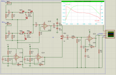
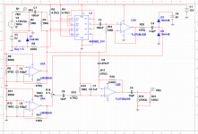
I edited the schematic to add the buffer after the switch, increase the input impedance after the digipot and adjust the filter accordingly, it now has a gain of -1.62 dB, adjusted the output amplifier to have a gain on 1.67 dB that can later be trimmed for overall unity gain. Also increased input impedance.
Now I'm not sure which is better, to take the output dc coupled between the output amplifier and the op amp generated reference line (4.9 V for now), or take the output ac coupled between the output amplifier and ground with a 470K resistor to preload to reduce output thump upon connection.
I'm not sure if I need to up the impedance on the output op amp feedback network or not.
I will still analyze it more in depth on Multisim specially because Proteus has issues converging and does weird stuff with the op amp references in place but how about that as for starters?
Attachments
The input and output conditions follow the same rules. Input and output coupling caps allow different DC conditions on either side. We know the conditions of the circuit because we fixed it. The input and output side are likely to be ground referenced. So the input and output resistors eg. R3,R4 and R5 should tie to ground. The output will need AC coupling since this at 4.9V.
U1B will need a series resistor to limit current into diodes for over voltage.
The feedback resistor network depends on a few things. Higher impedance allows non polar caps but introduces noise. The buffer can operate at higher impedance and scores over the inverter in this regard, where a second inverter is needed for gain make up and polarity correction. In this case the gain is low so additional noise will be low. The output load of the opamp is the input impedance of the connected equipment in parallel with the feedback network.
In short, determine the load and the type of capacitor you want to use in the feedback network.
Is the 20-20K filter for out of band noise? Filters close to the audio band introduce phase shift which will affect sound quality.
Okay so I'll reference both input and output to ground.
I plan to connect the output to an amplifier or powered speakers so their input impedance shouldn't be less than 10-20K I presume. I don't want to load the op amp too much with the feedback network that's why I'm thinking about a higher impedance network.
If I have to use non polar caps then I might just put two polarized caps back to back.
Yes it's to filter out of band noise including power supply switching noise and noise from the digital section where an Arduino or Atmega uC will control the digipot and IR receiver. All I know is that it needs to have a negative slope phase graph to not cause a problem; the phase shift is not a function of frequency.
Do you suggest I adjust the filter to a wider band or is there another solution?
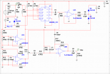
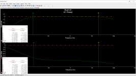
Verified on Multisim with the 10V spice model for the 4066. Added the resistor before the diodes, referenced the input and output to ground, adjusted the output amplifier gain again to make up for the new resistor.
In the distortion analysis is shows zero distortion from 10 to 40KHz which feels sketchy.
In the distortion analysis is shows zero distortion from 10 to 40KHz which feels sketchy.
Attachments
It is best practice to use PSU decoupling caps close to the power pins of the opamp. 0.1uF in parallel with 1 - 10uF. In this case the +V since the other is ground.
Filtering for the supply depends on how it is derived. Generally if a simple Vreg is used, an LC filter is recommended.
Capacitor choice depends on how far you wish to follow current wisdom about sound quality. A capacitor study showed that the best types are ceramic, polystyrene and polypropylene. The worst types, polyester and electrolytic. Polycarbonate sits in the middle. So the recommendation is to use non-electrolytic where it can be avoided. Where electrolytics are to be used, try and apply them where they have proper DC bias. In this case the only place that might need an electrolytic is from the buffer to the Digipot and it is biased because one side is 4.9V and the other 2.5V. Ceramic and polyester types are also available up to several uF. You might be limited by what is available in your parts bin.
The previous values for the feedback network are better. Remember the inverting input is high impedance so the load is 57K. Strangely, you have 4.7K after the Digipot. To be of benefit to the Digipot, attenuation has to be before.
Listen / scope Arduino for noise. Electronic music can have sub-harmonics but if your speakers can't reproduce them then you can limit to the ability of the speakers. 96KHz sampling is 48Khz bandwidth. You could start there and reduce as required. Phase shift is always a function of frequency.
You can also try decoupling the ground between the digital stuff and analog stuff. by inserting a resistor/inductor in the ground. You should avoid using common supplies for analog and digital. If analog has an independent supply, then ground currents wont be shared with the digital section. Noise problems occur when digital and analog currents mix. Not being familiar with Arduino I would look for advice in some of the other threads that use this type of platform. There are also methods to opto-couple control signals. All depends how fussy you are.
Distortion evaluation is three parts:
SS switch
Opamps
Digipot
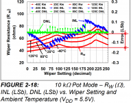
In reality the switch resistance graph needs to be interpreted differently from how it was shown. The switches do not encounter the full swing of the Digipot. This was a representation to highlight the principle which still stands to demonstrate best practice.
The voltage appearing across the switch will be a small fraction of the input signal, since it forms a potential divider with 1M input impedance. Meaning you can probably change the previous assessment of 0.005% to 0.0005%.
The distortion contributions of the opamp and Digipot are probably higher. To see if Mulitisim is configured correctly, reduce the input bias resistor to 1K which should provoke distortion. Also load the output suitably.
SS switch
Opamps
Digipot
In reality the switch resistance graph needs to be interpreted differently from how it was shown. The switches do not encounter the full swing of the Digipot. This was a representation to highlight the principle which still stands to demonstrate best practice.
The voltage appearing across the switch will be a small fraction of the input signal, since it forms a potential divider with 1M input impedance. Meaning you can probably change the previous assessment of 0.005% to 0.0005%.
The distortion contributions of the opamp and Digipot are probably higher. To see if Mulitisim is configured correctly, reduce the input bias resistor to 1K which should provoke distortion. Also load the output suitably.
The power supply will probably be a 12V SMPS followed by a DC-DC converter then a LM7812 linear regulator with capacitors everywhere. All the inductors I got are low Q but they really did help kill the hiss when I was trying something in this project. I had the LC filter the power input to a 555 based charge pump running at 40Khz. I know I should have put it on the op amps side but that was a quick trial on a breadboard so it was just easier at the time. I'll probably add an inductor between both grounds but they need to be connected. The digipot is not a problem at all, it can take power and ground on the digital side. They'll probably tie at the supply, like a star ground.
The 4.7K after the digipot is so that the 2nF cap before the final amplifier, can do its low pass filtering duties. There must be some resistance for the capacitor to create a voltage drop across. The filter attenuation is a burden and not intended, it's caused by the 4.7K and 1M resistive voltage divider and the 10nF and 2nF capacitive voltage divider, adding up to the -1.62 dB.
Wow I didn't know about these capacitor preferences. I mostly have ceramic and electrolytics, ceramics in values below 1uF only unfortunatly. I also have some tantalum caps, how do they stand up against the rest? I have a few non-polarized capacitors that I'm almost certain they're not ceramic but they are sort of dipped in a shiny yellow cover. I do not know if they are poly-ester, -styrene, -propylene or -carbonate. I changed the input and buffer coupling caps to 100nF as they won't affect the response with 1M bias resistors. These I guarantee to be ceramic.
The Arduino or Atmega should be controlling the 4066s, the digipots and reading IR signals. Maybe reading status from a Bluetooth module and maybe sample the audio somewhere before the digipot which I also don't want interfering much. I probably need to scope/listen to it insitu. The Arduino will only sample the audio to determine if a particular input port has a device connected to it. It's just a microcontroller with a 16Mhz crystal and a LDO reg that I'll bypass probably. I will only use opto couplers if I take matters to the point where I use separate toroidal transformers for the analog and digital parts
It's what I studied in DSP maybe I got something wrong, that was a while back. I did some adjustments and got the filtering to be at 15 & 35K, the phase varies about 94 degrees from 20 to 20K.
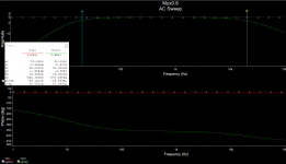
Changed the input bias resistor to 1K and loaded the ouput with 10K, Multisim output zero distortion for the whole frequency range. I think the digipot will not introduce much distortion, same scenario, wiper resistance changes about 23 ohms in comparison to 1.047M which is 0.000022%. I'm not sure how to assess the opamps for distortion.
The 4.7K after the digipot is so that the 2nF cap before the final amplifier, can do its low pass filtering duties. There must be some resistance for the capacitor to create a voltage drop across. The filter attenuation is a burden and not intended, it's caused by the 4.7K and 1M resistive voltage divider and the 10nF and 2nF capacitive voltage divider, adding up to the -1.62 dB.
Wow I didn't know about these capacitor preferences. I mostly have ceramic and electrolytics, ceramics in values below 1uF only unfortunatly. I also have some tantalum caps, how do they stand up against the rest? I have a few non-polarized capacitors that I'm almost certain they're not ceramic but they are sort of dipped in a shiny yellow cover. I do not know if they are poly-ester, -styrene, -propylene or -carbonate. I changed the input and buffer coupling caps to 100nF as they won't affect the response with 1M bias resistors. These I guarantee to be ceramic.
The Arduino or Atmega should be controlling the 4066s, the digipots and reading IR signals. Maybe reading status from a Bluetooth module and maybe sample the audio somewhere before the digipot which I also don't want interfering much. I probably need to scope/listen to it insitu. The Arduino will only sample the audio to determine if a particular input port has a device connected to it. It's just a microcontroller with a 16Mhz crystal and a LDO reg that I'll bypass probably. I will only use opto couplers if I take matters to the point where I use separate toroidal transformers for the analog and digital parts
It's what I studied in DSP maybe I got something wrong, that was a while back. I did some adjustments and got the filtering to be at 15 & 35K, the phase varies about 94 degrees from 20 to 20K.
Changed the input bias resistor to 1K and loaded the ouput with 10K, Multisim output zero distortion for the whole frequency range. I think the digipot will not introduce much distortion, same scenario, wiper resistance changes about 23 ohms in comparison to 1.047M which is 0.000022%. I'm not sure how to assess the opamps for distortion.
Attachments
Last edited:
Anything passing signal should be on the analog PSU side. This includes the Digipot despite its name and controls.
Distortion evaluation of the Digipot is not so simple. It is a collection of switches above and below the wiper. Therefore relative change of resistance behavior is the distortion mechanism, not load impedance.
Distortion of opamp from datasheet.
I prefer tantalum to alu electrolytic. Not everyone does. You can add parallel ceramic regardless.
If Mulitisim is still zero distortion, then you are reading signal generator or not configured correctly. Check example circuits if there are any.
Last edited:
Do you mean the relative change of resistance across the different wiper positions? But the wiper position will not be changed at audio frequency rates. I use the MCP4131-103 digipot and that's the only figure I assume to to be useful for distortion calculations. There are values for INL and DNL but I'm not sure that we're interested in these. If you could point me in the correct direction that would be awesome.
In the last schematic I posted, I only need 2 electrolytics, the 2.2 uF between the buffer and digipot which is biased 4.9 - 2.5 so there's no problem and the output 10 uF cap which is also biased, 4.9 - 0.
I'm still checking Multisim for errors.
In the last schematic I posted, I only need 2 electrolytics, the 2.2 uF between the buffer and digipot which is biased 4.9 - 2.5 so there's no problem and the output 10 uF cap which is also biased, 4.9 - 0.
I'm still checking Multisim for errors.
The largest jump is before the buffer output resistance and at the diode's junction. 0.0029% to 0.0149%. That's at 1M input bias and 15K load. I'm not sure how to solve that.
Distrotion at all points in order;
after input cap: 0.001818%
after 4066 sw: 0.00181799% (decreased ??)
after buffer input cap: 0.0029004%
buffer output: 0.00294387%
after digipot input cap: 0.0149069%
after digipot: 0.0149069%
after BPF/output amp input: 0.0431737%
after output amp: 0.0450913%
at load: 0.0484176%
At 1K input bias and 15K load:
after input cap: 0.0021989%
after 4066 sw: 0.0021989%
after buffer input cap: 0.0022008%
buffer output: 0.00220706%
after digipot input cap: 0.00216017% (decreased ??)
after digipot: 0.00216017%
after BPF/output amp input: 0.00187725% (decreased)
after output amp: 0.00186541% (decreased)
at load: 0.00184102% (decreased)
Last edited:
It is not logical that with the 1K bias there is no distortion contribution after the switch. Also the way the distortion behavior changes suddenly. The section after the buffer has to behave consistently, which it doesn't. So I suspect either a sim issue or change of DC bias. Check the signal at all sections swings around the DC bias you designed.
Also break up the design into sub sections and test those separately beginning with the switch and the bias resistor on the output. I ran a simple sim using a JFET as the switch and the behavior was as expected. With the 1M very little distortion at all. With 1K 0.027%.
Also break up the design into sub sections and test those separately beginning with the switch and the bias resistor on the output. I ran a simple sim using a JFET as the switch and the behavior was as expected. With the 1M very little distortion at all. With 1K 0.027%.
- Status
- This old topic is closed. If you want to reopen this topic, contact a moderator using the "Report Post" button.
- Home
- Source & Line
- Analog Line Level
- Yet another mux, 4052, 4053 or 4066?