Think again:Well, the same speakers (Bose Syncom tested) have no problem with filling the room with bass with my 50 years old amplifier (Dual CV40) so I don't think the problem is with them.
1) Then it is your 50 year old amplifier which is NOT ruler flat.
2) Besides the quite possible "loudness" boost as mentioned above by others, its damping factor must be horrible, so artificially boosting Bass at resonance.
It´s a very dated design: single supply fed, with output coupling capacitors.
So you have large, *old* , most probably high ESR caps in series with your speakers ... think about their effect on frequency response.
3) While LM3886 is a high damping ruler flat amplifier, which if you wish can go down to DC, go figure.
So nothing to "correct" there.
Last edited:
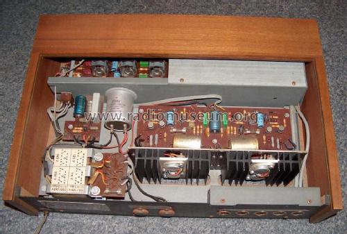
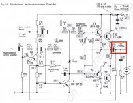
You made me curious so I checked CV40 schematic ... looks like all of us guessed right:
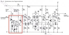
1) CV40 does have a Loudness circuit:
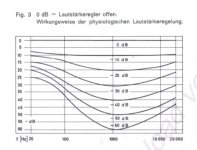
2) whose curves are :
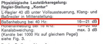
3) where they admit 16 to 21dB boost at 40 Hz
(room filling Bass indeed 🙄 )
4) and to boot shows the capacitors in series with speakers.
5) and amplifier design and topology *are* real dated.
Not dissing it, by far, the amplifier was excellent ... for 1968 .
1) CV40 does have a Loudness circuit:
2) whose curves are :
3) where they admit 16 to 21dB boost at 40 Hz
(room filling Bass indeed 🙄 )
4) and to boot shows the capacitors in series with speakers.
5) and amplifier design and topology *are* real dated.
Not dissing it, by far, the amplifier was excellent ... for 1968 .
Attachments
Hello everybody, thanks for all the replies.
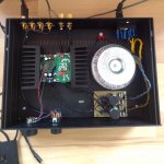
A few people mentioned the schematic lacking, maybe I was not clear. As I mentioned in my first post, I built it with the vales of BrianGT's design. I tried to replicate that on a different pcb. You know, like this:
DIY LM3886 Chip Amplifier (Gainclone) Kit
With the difference being a 2.2 uF input cap because my pcb had a slot for it, without the 0.1uF caps paralel to 100uF decoupling caps and without the snubber in psu board. I also added a picture of how it looks like. Since I did not like the ground design of the pcb I cut some traces and did a star ground on the pcb the way described by Andrew C. Russell with a hum breaking resistor. Zobel network is on the back side of the pcb since it was designed without it.
After seeing JMFahey's analysis of my other amp, I guess I was spoiled when it came to lower frequencies. But I found it weird, playing a dub/reggae record (from a OPA2134 based RIAA preamp) and while mids and highs are clearer than I have ever heard, the bassline is almost not distinguishable (for my spoiled ears). Maybe I should look into a way to boost the bass.
Attachments
So build a little op-amp based tone control board with bass and treble controls that you can turn all the way up.
Your PS wires need to be thickened . On the three screws of PS input apply a pair of low ESR 10000uf capacitors . The loudspeaker ground take from the same fork on the middle screw along the in coming PS ground . As you enforced the ground with extra wire , you need the do the same for the +&-V but with double 1mm wires for each linking the screws by separate forks and not from the PCB . Optionally you need to thicken the feet of the IC by the leads of the added capacitors (are magnetic) only the 2 +V , -V and the output . To go extreme, glue with epoxy 1mm of steal sheet(transformer iron better) upon the IC on covering the writings. Pioneer car radios use U shaped extrude to be screwed on eider sides .
Your PS wires need to be thickened . On the three screws of PS input apply a pair of low ESR 10000uf capacitors . The loudspeaker ground take from the same fork on the middle screw along the in coming PS ground . As you enforced the ground with extra wire , you need the do the same for the +&-V but with double 1mm wires for each linking the screws by separate forks and not from the PCB . Optionally you need to thicken the feet of the IC by the leads of the added capacitors (are magnetic) only the 2 +V , -V and the output . To go extreme, glue with epoxy 1mm of steal sheet(transformer iron better) upon the IC on covering the writings. Pioneer car radios use U shaped extrude to be screwed on eider sides .
Thanks for the suggestions, only thing I could try out on a sunday was using the same enameled wire for the voltage lines too, which makes sense, should have thought about it, and it already improved the bass response. Will try thicker wires for power when I get them. When I think about it, I should have included a picture in my first post.
Leadbelly, 2.2uF 50V metallized polyester film caps (MKS2) are indeed that small.
Wiring and similar changes are not bad, quite the contrary, but best case will improve fractions of a dB ... if that much.}
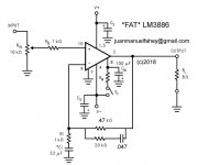
Since you are comparing it to a *old* not exactly flat amplifier, and to boot using old middle quality speakers, I suggest you try this instead:
[Fat LM3886 schematic]
Smoothly rising below 160Hz, + 6dB plateau boost between 40 and 80 Hz.
Try it and post results 🙂
As a side note, your speakers are at least 20 years old, maybe 30, and foam edges must be rotten by now.
Did you refoam them?
There are replacement kits available and job is "doable" at home just being somewhat careful.
Attachments
Why do you think so? IMHO LF response is a matter of the surrounding passive components, especially the capacitors, rather than the IC itself.With 4 Ohms the LM3886 has problems with f < 50 Hz.
Best regards!
I don't think so Mr. Kay, lack of "muscle grip" of a chipamp can be felt like a "thin sound". Perhaps this is a matter of ability of the chipamp (and PSU) of handling the low-freq transients.
Chipamp is flat down to DC, including "muscle grip" which driving an electrodynamic transducer (vulgo: "louspeaker") means peak current capability, at *any* Frequency.
Typically 11.5A , guaranteed minimum 7A.
Datasheet shows .005% distortion when delivering 60W RMS into a 4 ohm load at 20 Hz , ... I´d call "not having any trouble" driving it.
Do you have any proof of the contrary?
Please post it here.
Typically 11.5A , guaranteed minimum 7A.
Datasheet shows .005% distortion when delivering 60W RMS into a 4 ohm load at 20 Hz , ... I´d call "not having any trouble" driving it.
Do you have any proof of the contrary?
Please post it here.
https://www.powerstream.com/Wire_Size.htm You find on American wire gauge the required thickness necessary . One mm is the maximum size can be used , as it has 17khz limit due to skin effect ,but as it shows the maximum power transmission current is 2.3 amps . Your wire size is better on condition you put many of it in parallel. As you also read on the table that if the wire chassis (steal) wired the current capability is much higher , on condition that these wires (enamel) are flowing upon the magnetic steal . Don't ask me the reason of these numbers , I am not American , but ask it to the invented of the fuse , Mr. T. Edison. To succeed your amplifier you MUST RESPECT the American's.
If the current was that high at 17kHz there may be a very slight roll off, it won't be, so there isn't, so forget it.
...One mm is the maximum size can be used , as it has 17khz limit due to skin effect...
You made this (off-point) claim on another thread.
If true, then it is impossible to connect a high power TV transmitter.
In fact we select wire for "negligible" resistance, so it causes "no" loss. The loss does rise with frequency, but if the wire is ample the small increase of resistance is still "no" effect. Do the math.
skin effect
https://en.wikipedia.org/wiki/Skin_effect
To transmit high power high frequencies it is no more wire but hollow tube of copper alloy . I am very thankful you remember my posts. See also Litz wire.
https://en.wikipedia.org/wiki/Skin_effect
To transmit high power high frequencies it is no more wire but hollow tube of copper alloy . I am very thankful you remember my posts. See also Litz wire.
Attachments

Last edited:
- Status
- Not open for further replies.
- Home
- Amplifiers
- Chip Amps
- Yet another LM3886 lacking bass thread.