"Loudspeakers do not ordinarily have high orders of nonlinearity because they are mechanical devices - higher orders of nonlinearity require large rapidly changing forces. This phenomenon is not uncommon in electronics, but it is
atypical in most mechanical device"
Here is the rest:
http://www.gedlee.com/downloads/AES06Gedlee_ll.pdf
So if the amplifier can have low order distiortion (2nd and/or 3rd in any mix) the lower the better and in that case will not be too dissimilar from speakers.
atypical in most mechanical device"
Here is the rest:
http://www.gedlee.com/downloads/AES06Gedlee_ll.pdf
So if the amplifier can have low order distiortion (2nd and/or 3rd in any mix) the lower the better and in that case will not be too dissimilar from speakers.
I am trying to get out the door to teach a class.
Tomorrow I will hook up the 600 Volt variable power supply and run this breadboard at the design 350 B+ volts.
DT
Why not use your power supply at 600 V?
Popilin,
Even a perfect model, particularly a perfect model has problems of its own. Two perfect 12AU7’s in a SPICE simulated SRPP may cancel perfectly, leading to unreal notching of the distortion. This problem only lives in a perfect SPICE simulation, it will not happen in a real circuit.
I like the test results too.
DT
Agree, however it is said that "ECC82 is very consistent sample to sample, they are consistently bad" Morgan Jones dixit, if memory serves, maybe both halves are consistent too, never knows.
Attachments
All,
12au7 optimized SRPP tested at 350 B+ volts. A bit of disclosure, the tube tested is a 9AU7 Amperex made in Canada, this one has an orange globe printed on it.
This Keysight N5752A is windows based, there is a sequence of pushing buttons and turning knobs I needed to be careful not to let smoke out of other items on the bench. This powersupply makes less noise than the Sorensen XT-250-0.250.
Output voltages and Harmonics listed below:
-1 Volt
-76.5 db 2nd Harmonic
-110 db 3rd Harmonic
-2 Volt
-70.5 db 2nd Harmonic
-103 db 3rd Harmonic
-5 Volt
-62 db 2nd Harmonic
-85 db 3rd Harmonic
-10 Volt
-56 db 2nd Harmonic
-73 db 3rd Harmonic
-113 db 4th Harmonic
-117 db 5th Harmonic
I have a nice NOS Phillips JAN 6DJ8 valve sitting here. Who wants to do the Merlin Optimized calculations and supply the resistor values for a 300 B+ volts supply? We will test it next.
DT
All,
12au7 optimized SRPP tested at 350 B+ volts.
What is the load?
To keep things simple, the same 18.45K as the last one.
DT
Then, this is not an optimized SRPP. 🙄
The circuit of post#1 uses a model of a Mullard ECC82, and optimize the load is tricky, even with LTSpice, you must run a lot of simulations.
Don't be lazy and make some tweak on the load. 😛😀
You are quite greedy Juan.😀
0.16% THD at 10 V is not bad at all. It's about the same THD I got in the un-optimized SRPP at 1V! Until this is 2nd and 3rd harmonic only it's fine.
You could use some feedback and reduce both gain and THD. It works very well and might be a better choice if you want to move the volume control at the output. The improvement in THD should be roughly proportional to gain reduction. It should work better without cathode bypass. So really in line with what you are doing.
Don't believe generic metropolitan stories about feedback. It always depends on the application....
.....
Don't be lazy and make some tweak on the load. 😛😀
Lazy? Not so much. Just wanting to share the fun!
Of the twin triodes that I tested in the half-mu circuit the 6DJ8 was by far the best performing.
Just saying if someone wants to do the optimization/simulation calculations I will test it.
DT
You are quite greedy Juan.😀
Maybe, I got carried away by emotion, I have not a distortion analyzer. 🙁
Lazy? Not so much. Just wanting to share the fun!
OK, here is
Attachments
0.16% THD at 10 V is not bad at all. It's about the same THD I got in the un-optimized SRPP at 1V! Until this is 2nd and 3rd harmonic only it's fine.
You could use some feedback and reduce both gain and THD. It works very well and might be a better choice if you want to move the volume control at the output. The improvement in THD should be roughly proportional to gain reduction. It should work better without cathode bypass. So really in line with what you are doing.
Don't believe generic metropolitan stories about feedback. It always depends on the application....
Wise words, you are right, as I do not need more than 1 V RMS, maybe I will build the 350 V version.
Anyway, feedback is against my religion, you cannot correct in the past an event in the present.
But keep it quiet. 😛😀
Maybe, I got carried away by emotion, I have not a distortion analyzer. 🙁
OK, here is


Okay Popilin,
We are cooking now. I am heading for the resistor crate to pick out some resistors.
For consistency you have done the design. We have the same LTspice and most likely the same quality valve model. I believe that there are skeptics. Many things are the same. The valve is different. We will see the results.
As Ian pointed out the input resistance of the analyzer is in parallel with the output. This time I am going to adjust the load resistor to compensate for the analyzer 100K being in parallel. Out of the gate the first pass will be with the specified 29.5K load resistor.
DT
ECC88 is not exactly 6DJ8, my friends. There is a 6DJ8 model in valves.lib. I am curious what are you going to compare. I comment end here.
I am heading for the resistor crate to pick out some resistors.
I am sorry to bother you, but can you please optimize the circuit for the ECC82/12AU7 before?
I turns out that I have a lot of them, and here an ECC88 cost more than 100U$S 🙄
Popilin,
See this post.
http://www.diyaudio.com/forums/tubes-valves/74903-survey-aikido-distortion-17.html#post4719609
DT
See this post.
http://www.diyaudio.com/forums/tubes-valves/74903-survey-aikido-distortion-17.html#post4719609
DT
Popilin,
See this post.
http://www.diyaudio.com/forums/tubes-valves/74903-survey-aikido-distortion-17.html#post4719609
DT
Even so, I think that you can optimize the thing even more, if you play a bit more on the load, 22K1//100K is about 18K, even with LTSpice you must try several values untill the null is reached, it is a bit more difficult with the iron solder and real resistors.
In this case, is Me who believe in the gold at the end of the rainbow. 😛😀
Edit: Thanks alot for your effort, and beautiful instrumental by the way.
Last edited:
http://www.diyaudio.com/forums/tubes-valves/74903-survey-aikido-distortion-17.html#post4720233
I think that the most safe for your analyzer is to put a 100K resistor in parallel with a 100K pot, then 100K(fix)//100K(pot)//100K(analizer) is about 33K, then you can go from almost zero to 33K of load resistance, a multiturn trimmer pot should be a good idea.
I think that the most safe for your analyzer is to put a 100K resistor in parallel with a 100K pot, then 100K(fix)//100K(pot)//100K(analizer) is about 33K, then you can go from almost zero to 33K of load resistance, a multiturn trimmer pot should be a good idea.
Last edited:
DT, when I had all the answers, they changed me the questions. 😛😀
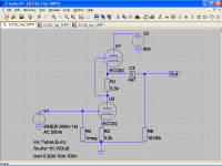
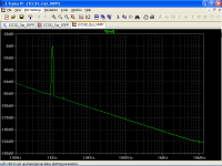
A simulation of circuit from post#1 with a 0.68μF capacitor

Very close to your result here
http://www.diyaudio.com/forums/tubes-valves/74903-survey-aikido-distortion-18.html#post4721214
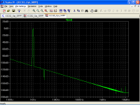
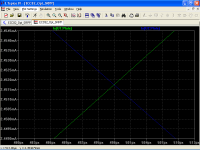
AC current through both triodes, with a 0.68μF cap

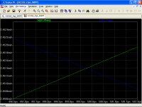
AC current through both triodes, with a 4.7μF cap

Here comes the part in that you will want to kill me, can you please make another measurement with a bigger cap? 🙂
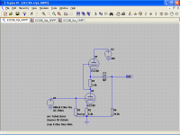
A simulation of circuit from post#1 with a 0.68μF capacitor
Very close to your result here
http://www.diyaudio.com/forums/tubes-valves/74903-survey-aikido-distortion-18.html#post4721214
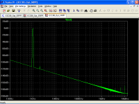
AC current through both triodes, with a 0.68μF cap
AC current through both triodes, with a 4.7μF cap
Here comes the part in that you will want to kill me, can you please make another measurement with a bigger cap? 🙂
Attachments
Last edited:
Many things are the same. The valve is different. We will see the results.
I must confess that I am anxious for results, if a poor AU7 can go to -84 dB 2nd harmonic, an ECC88 should be better. 🙂
I must confess that I am anxious for results, if a poor AU7 can go to -84 dB 2nd harmonic, an ECC88 should be better. 🙂
Hello Popilin and All,
Last night I put the 6DJ8 into the breadboard and began testing the SRPP with different cathode resistors; 309R, 619R and 1K. Part way into the 1K test the Keysight power supply ceased to function. Other cathode resistor values will need to wait. The power supply is in warranty; it went to the Roseville Keysight repair facility this afternoon.
For the 309R cathode resistor the optimized load was 2.643K ohms, at 1 volt output the 2nd harmonic was -73db, 3rd harmonic was -88db.
For the 619R cathode resistor the optimized load was 10.53K ohms, at 1 volt output the 2nd harmonic was -85db, 3rd harmonic was -112db.
For the 1K cathode resistor the optimized load was 21.22 ohms, at 1 volt output the 2nd harmonic was -83db.
Interesting to me, not surprising, is that if the designer selects a particular cathode resistor value the adjustable resistor (load) settles in at different value for each specific value of cathode resistor selected. I did not measure it; I assume that the current through the load settles in at a symmetrical Push Pull swing. Conversely if the designer has a particular load intended there is a specific cathode resistor value that will achieve a balanced push pull swing and minimize distortion with that specific load in mind.
More fun!
DT
Hello Popilin and All,
Last night I put the 6DJ8 into the breadboard and began testing the SRPP with different cathode resistors; 309R, 619R and 1K. Part way into the 1K test the Keysight power supply ceased to function. Other cathode resistor values will need to wait. The power supply is in warranty; it went to the Roseville Keysight repair facility this afternoon.
Hi DT, Thank you for sharing, I am sorry for your PSU by the way.
Hope it will be repaired soon for more results. 😉😛
Then, so far very close to the 9AU7. 😕For the 309R cathode resistor the optimized load was 2.643K ohms, at 1 volt output the 2nd harmonic was -73db, 3rd harmonic was -88db.
For the 619R cathode resistor the optimized load was 10.53K ohms, at 1 volt output the 2nd harmonic was -85db, 3rd harmonic was -112db.
For the 1K cathode resistor the optimized load was 21.22 ohms, at 1 volt output the 2nd harmonic was -83db.
Some people must not be very happy about this. 😛😀
Indeed, in Merlin's articleInteresting to me, not surprising, is that if the designer selects a particular cathode resistor value the adjustable resistor (load) settles in at different value for each specific value of cathode resistor selected. I did not measure it; I assume that the current through the load settles in at a symmetrical Push Pull swing. Conversely if the designer has a particular load intended there is a specific cathode resistor value that will achieve a balanced push pull swing and minimize distortion with that specific load in mind.
Rk optimum = (2 Rload + Ra) / (μ - 1)
Amazing article BTW, full of equations, I like equations very much.
Agree.More fun!
DT

- Status
- Not open for further replies.
- Home
- Amplifiers
- Tubes / Valves
- Yet another ECC82/12AU7 Line Preamp