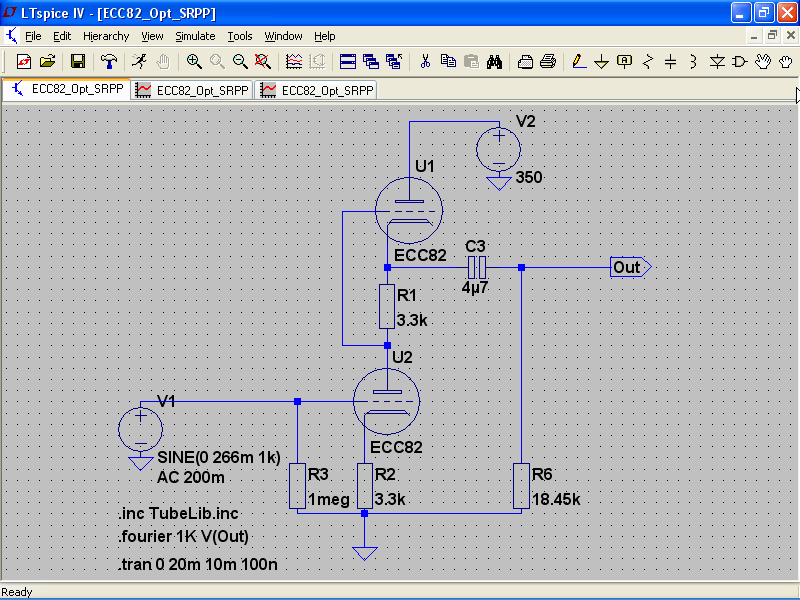
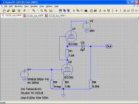
As the ECC82/12AU7 is the cinderella of valves, after reading the article of Merlin Blencowe "The Optimized SRPP Amp" I tried this only as a thought experiment
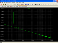
The distortion spectrum is just too good to be true

Has someone tried this on practice?
In other words: how does it sounds?
The distortion spectrum is just too good to be true
Has someone tried this on practice?
In other words: how does it sounds?
Attachments

I used a very similar circuit on the front of a solid state amp and it sounded very clean.
Hi, thanks for your reply.
I have build a lot SRPPs but never optimized it.
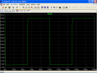
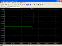
There is a small edge on the square wave and I have no clue about it.
Reducing cathode resistors the edge disappears, but the output load must be too low.
Attachments

Perhaps grid stopper resistors on either the upper or lower or even both sections will help. The basic design though should sound very nice, quite similar to one of mine. I use lower B+ and lower cathode resistors as well. The problem with loading is typical of a single stage like this. I calculate a Z out of about 4K and a idle current of just about 2.2ma. I prefer the sound when the idle current is about 6-7 ma (1/4 to 1/3 of I max for any given tube), cathode resistors of 270R and a B+ of about 220. At those setting the Z out drops to about 2.8K.
With a 3K3 cathode resistor the tube will be running at a very low current. Do a .op sim to find the current you are operating at. Low quiescent current means low drive capability. You should also know that there is an optimum load for an SRPP that gives minimum distortion. You may just have hit the right value by accident. Also you have a very high HT voltage. One limitation of sims is they do not stop you using silly supply voltages. I once did a sim of an EL84 SE output stage. I tried tweaking the HT and in doing so accidentally added a zero to the HT volts. The performance was amazing. At first I thought i had found a seet spot until I noticed the HT was 3000V!
Cheers
Ian
Cheers
Ian
Perhaps grid stopper resistors on either the upper or lower or even both sections will help. The basic design though should sound very nice, quite similar to one of mine. I use lower B+ and lower cathode resistors as well. The problem with loading is typical of a single stage like this. I calculate a Z out of about 4K and a idle current of just about 2.2ma. I prefer the sound when the idle current is about 6-7 ma (1/4 to 1/3 of I max for any given tube), cathode resistors of 270R and a B+ of about 220. At those setting the Z out drops to about 2.8K.
Hi, thanks for your reply.
The SRPP does not need grid stoppers on the upper triode, as the ECC82 has low gm it does not need grid stopper on the lower triode either.
The design is intended to use with an output buffer, so output impedance is not that important.
With a 3K3 cathode resistor the tube will be running at a very low current. Do a .op sim to find the current you are operating at. Low quiescent current means low drive capability. You should also know that there is an optimum load for an SRPP that gives minimum distortion. You may just have hit the right value by accident. Also you have a very high HT voltage. One limitation of sims is they do not stop you using silly supply voltages. I once did a sim of an EL84 SE output stage. I tried tweaking the HT and in doing so accidentally added a zero to the HT volts. The performance was amazing. At first I thought i had found a seet spot until I noticed the HT was 3000V!
Cheers
Ian
Hi Ian, thanks for your reply.
The circuit was already optimized using Merlin's equations as a start point and try and error to final tuning, as I said before, reducing cathode resistors output load resistor must be too low and I do not want enormous coupling capacitors.
In fact, quiescent current is too low, about 2.45 mA, but the idea is to use a buffer, be in mind that optimized SRPP needs a fixed load.
2.45mA should be fine for the 18K load. The circuit as it stands should be able to drive about 36V rms into 18K so you have plenty of headroom.
Personally I have never found a good correlation between spice predicted distortion and the actual distortion measured in the circuit. Spice always underestimates distortion and some models are much worse than others. It would be interesting to see some measurements of the actual circuit.
Cheers
Ian
Hi Ian, thanks for your reply, very kind for your part as ever.
Excellent news, this is one thing that I wanted, some information from an expert.
I am tempted to think that the small edges on the square wave are due to some valve capacitances charged/discharged through cathode resistors. What do you think about this? My concern is that a harsh on treble, not audible "per se" due to my tinnitus, would ruin the sound without any clue, like high frequency oscillations.
Unfortunately I only have an old scope and a couple of multimeters, however my experience is different than yours, comparing FFT plots from another friend (Digital scope/audio analyzer) LTSpice predictions was amazing, even comparing a test circuit in Morgan Jones book, LTSpice results was very close to those published in the book. I use Norman Koren models, and that simulation is useful to discard bad models.
2.45mA should be fine for the 18K load. The circuit as it stands should be able to drive about 36V rms into 18K so you have plenty of headroom.
Excellent news, this is one thing that I wanted, some information from an expert.
I am tempted to think that the small edges on the square wave are due to some valve capacitances charged/discharged through cathode resistors. What do you think about this? My concern is that a harsh on treble, not audible "per se" due to my tinnitus, would ruin the sound without any clue, like high frequency oscillations.
Personally I have never found a good correlation between spice predicted distortion and the actual distortion measured in the circuit. Spice always underestimates distortion and some models are much worse than others. It would be interesting to see some measurements of the actual circuit.
Cheers
Ian
Unfortunately I only have an old scope and a couple of multimeters, however my experience is different than yours, comparing FFT plots from another friend (Digital scope/audio analyzer) LTSpice predictions was amazing, even comparing a test circuit in Morgan Jones book, LTSpice results was very close to those published in the book. I use Norman Koren models, and that simulation is useful to discard bad models.
The 12AU7 SRPP was the first valve preamp I made a long time ago but I still have it. At the time B. Aloia was very popular in Italy both for his solid state amplifiers and valve amplifiers. The optimized SRPP with ECC88 was one of his favourite and actually was also used as voltage amplification stage in his later hybrid amp for DIY'ers.
Despite of this I didn't optimize anything and the results were very good anyway, IMHO.
I have found my notes and I measured 1 V r.m.s with about 0.13% THD and 5 V r.m.s @ 1.2% THD. I only needed 0.5V to drive the power amp in the worst case. At 0.5V output THD was 0.08%.
The preamp uses just over 250V supply, 1K cathode resistors for about 4 mA current and 1 uF +1 Meg at the output. Only the bottom cathode is bypassed with 220 uF. The input impedance of the power amp I was driving was 47K and this is what I used to run my measurements. Gain is about 16x, a bit too much but the preamp is usable with no problems.
Power supply needs to be really good.
Last edited:
Hi Pierpaolo, good to see you around here!
You still owe me a picture of your preamp.
On paper, ECC88 seems better for optimized SRPP due to higher mu and lower Ra, but in simulations I still don't achieve so good results.
I have build a lot of SRPP preamps with the ECC82 without optimizing them and they sound very good, however now I want to put the volume pot between the SRPP and a buffer, then lowering the pot thermal noise and reduce greatly fase shifts, that's why I need ultra low distortion.
Last edited:
You still owe me a picture of your preamp.
Ok. It's in a shoe box somewhere, I need to find it. But it is nothing really special. It was actually made with all salvaged parts except the valves. Total cost: the equivalent of 5 euros for two National branded 12AU7's (made in China). Equivalent because at the time we didn't have the Euro, yet.
Ok. It's in a shoe box somewhere, I need to find it. But it is nothing really special. It was actually made with all salvaged parts except the valves. Total cost: the equivalent of 5 euros for two National branded 12AU7's (made in China). Equivalent because at the time we didn't have the Euro, yet.
No problem, I can wait. 😀
...... Spice always underestimates distortion and some models are much worse than others. It would be interesting to see some measurements of the actual circuit.
Cheers
Ian
All,
Today I am putting this circuit together on the breadboard to run a FFT to see harmonics.
The B+ voltage will take an effort. There is a new power supply in a box that I will need to set up and get running.
Could be a day or so.
DT
All,
Today I am putting this circuit together on the breadboard to run a FFT to see harmonics.
The B+ voltage will take an effort. There is a new power supply in a box that I will need to set up and get running.
Could be a day or so.
DT
Cool. Look forward to seeing the results.
Cheers
Ian
Ian,
I ran out of time today and did not change out the B+ power supply yet.
I did test the circuit with 258 B+ volts. I used the exact resistor values called out by Popilin on his schematic. The only thing different was the output capacitor, that was 0.68 uf.
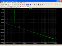
Using the U8903B I got;
-69db 2nd harmonic
-96db 3rd harmonic
4th and higher harmonics are in the weeds.
Interestingly, I got the same results at 1 volt and 2 volts output.
DT
I ran out of time today and did not change out the B+ power supply yet.
I did test the circuit with 258 B+ volts. I used the exact resistor values called out by Popilin on his schematic. The only thing different was the output capacitor, that was 0.68 uf.
Using the U8903B I got;
-69db 2nd harmonic
-96db 3rd harmonic
4th and higher harmonics are in the weeds.
Interestingly, I got the same results at 1 volt and 2 volts output.
DT
So 2H was some somewhat higher than predicted by Spice. If I read the spec right, the unbalanced input impedance of the U8903B is 100K. If you used the 18K design load then the actual load with the U8903B would have been 15K.This would account for part but not all of the difference between Spice and the real world. Getting the same result at 1V and 2V is puzzling. Can you post the actual spectra of both cases?
Cheers
ian
Cheers
ian
So 2H was some somewhat higher than predicted by Spice. If I read the spec right, the unbalanced input impedance of the U8903B is 100K. If you used the 18K design load then the actual load with the U8903B would have been 15K.This would account for part but not all of the difference between Spice and the real world. Getting the same result at 1V and 2V is puzzling. Can you post the actual spectra of both cases?
Cheers
ian
Ian,
Oops I did a misfire.
I went back to take a look at the 1 volt output. My first report was in error.
The 1 volt output is;
2nd harmonic -76 db
3rd harmonic is -106 db
4th and higher are in the weeds.
This Keysight machine is new to me, I am working with the tech support people learning how to output the graphics.
Also I am constructing a low noise/distortion op-amp buffer, details taken from Guido Tent's article in the most recent Linear Audio publication to buffer these line level tube circuits.
DT
I ran out of time today and did not change out the B+ power supply yet.
I did test the circuit with 258 B+ volts. I used the exact resistor values called out by Popilin on his schematic. The only thing different was the output capacitor, that was 0.68 uf.
For 250V +B, try this
Attachments
The optimized SRPP is very good as preamplifier, input stage in valve power amps and voltage amplifier in hybrid amps. The only potential issue here might be the output volume pot. With no attenuation at the input I would make sure the preamp behaves well also for rather higher output than 1-2 Volts.
I know it is a bit expensive but a properly made transformer volume control at the input for me is the best solution. It can also improve quite a bit noise figures while providing easily 20-30K input impedance.
I know it is a bit expensive but a properly made transformer volume control at the input for me is the best solution. It can also improve quite a bit noise figures while providing easily 20-30K input impedance.
Ian,
Oops I did a misfire.
I went back to take a look at the 1 volt output. My first report was in error.
The 1 volt output is;
2nd harmonic -76 db
3rd harmonic is -106 db
4th and higher are in the weeds.
This Keysight machine is new to me, I am working with the tech support people learning how to output the graphics.
Also I am constructing a low noise/distortion op-amp buffer, details taken from Guido Tent's article in the most recent Linear Audio publication to buffer these line level tube circuits.
DT
That makes more sense. Distortion in triodes is directly proportional to output level so you would expect the 1V figure to about 6dB lower than the 2V level. Still a long way above the spice prediction.
Cheers
Ian
- Status
- Not open for further replies.
- Home
- Amplifiers
- Tubes / Valves
- Yet another ECC82/12AU7 Line Preamp