It's a MatLab script, quite programmatic to set the parameters.nice to see the sim !! we knew dispersion would be best if you could make both dimension small, only reason for taking line is less los of dB at doubling distance, and being able to go low and get high spl without having low dispersion 🙂 but nice program , what is it ?
Script published!
I have published the script now if someone wants to try it 🙂
Check this thread: http://www.diyaudio.com/forums/software-tools/298622-script-calculate-sound-radiation-patterns.html
I have published the script now if someone wants to try it 🙂
Check this thread: http://www.diyaudio.com/forums/software-tools/298622-script-calculate-sound-radiation-patterns.html

Very nice!!!, when i got some time i will def look at it thanks for all the hard work!!! and sharing it!
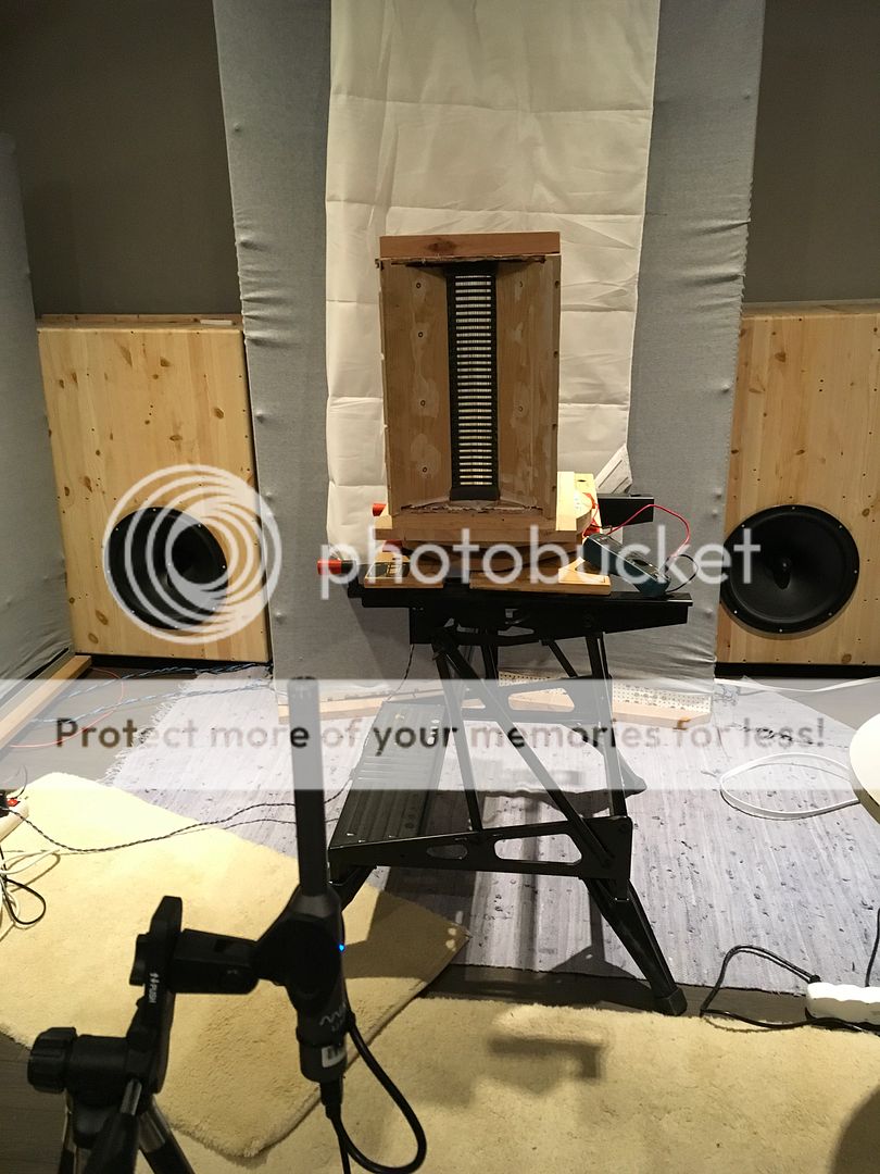
First steps towards the improved AMT has been taken.
It was about making the present AMT non-OB.
First the AMT was removed from the baffle:
And then I made a box like an owl's nesting-box:
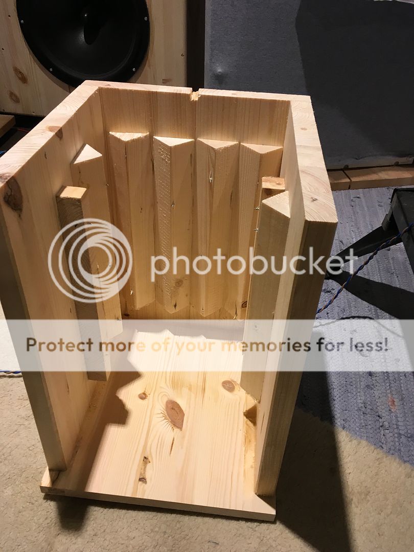
Filled it with glass wool insulation:

And put some reticulated foam directly on the motor:
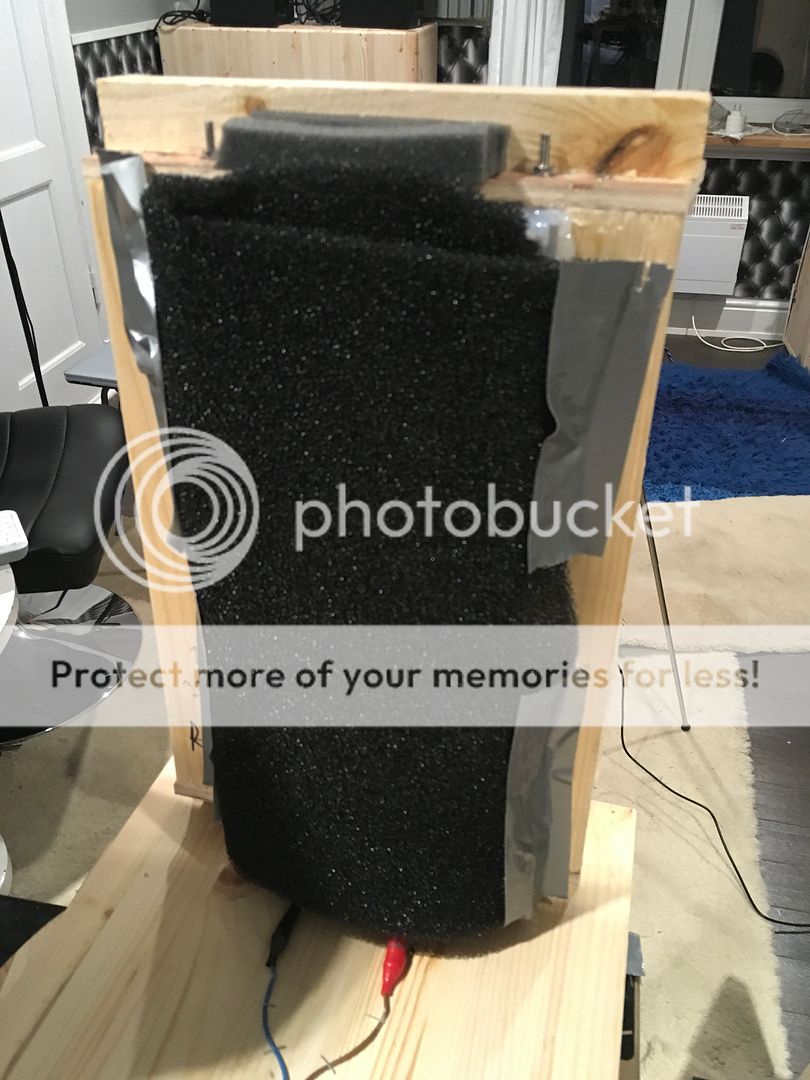
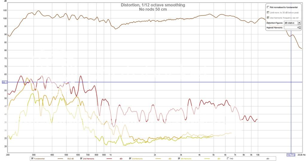
With this result:
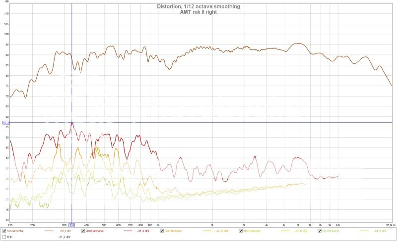
Compare this with when the AMT was in the baffle:
It was about making the present AMT non-OB.
First the AMT was removed from the baffle:
And then I made a box like an owl's nesting-box:
Filled it with glass wool insulation:
And put some reticulated foam directly on the motor:
With this result:
Compare this with when the AMT was in the baffle:
Very nice!
Your distortion products are very much lower than what your signal is.
That dip at 1000 hertz may be related to a reflection.
343 (speed of sound in meters/second at 20 degrees C) / 1000 = 0.343 meters for full wavelength. Half wavelength also can accommodate a reflection and a resulting null in the frequency response.
Why such a large rear enclosure?
Very nice!
Your distortion products are very much lower than what your signal is.
That dip at 1000 hertz may be related to a reflection.
343 (speed of sound in meters/second at 20 degrees C) / 1000 = 0.343 meters for full wavelength. Half wavelength also can accommodate a reflection and a resulting null in the frequency response.
Why such a large rear enclosure?
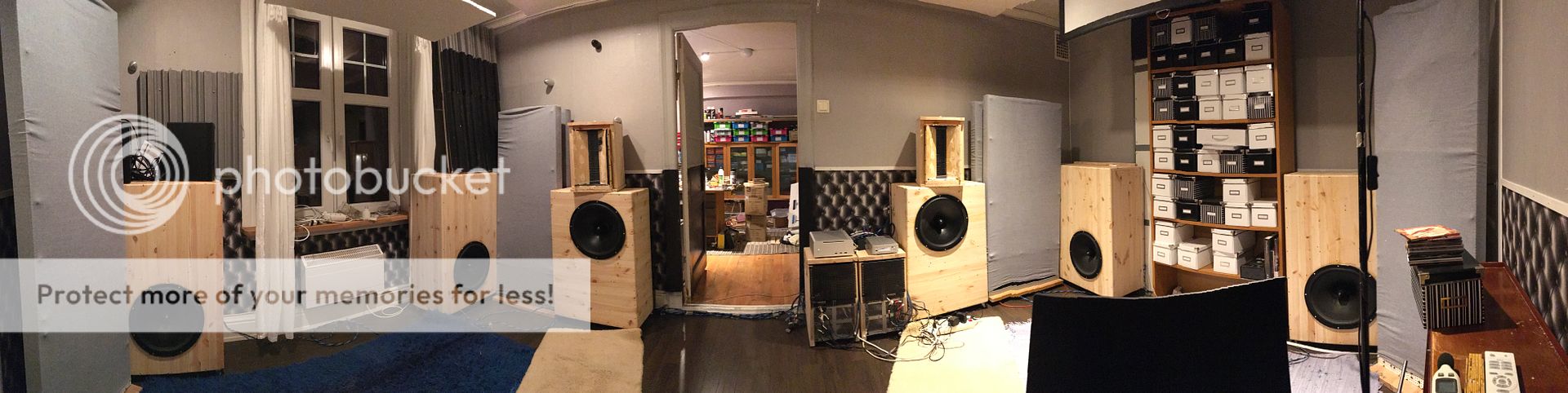
They were made of left overs from the build of the front bass speakers in my new setup.
Here's a 180 degree panorama picture taken from the sweetspot of the new setup:
For how long does the membrane needs to be baked? I’m using 7um aluminium and I used 7um Mylar and 10um . I tried to bake the diaphragm at 170 Celsius for 25 minutes but it didn’t keep the shape very well.thanks!
I can`t really find anything about the 3M 74 tape. I can`t even find to buy it. I forgot to say that I`m from the UK. Maybe is not available here.
I was thinking to look from what is made, so I can figure out how long to leave mine in the oven.
The last one I made it right now I use 10um mylar. What do you suggest? I`ll keep it in the folding tool until I`m sure what to do
I was thinking to look from what is made, so I can figure out how long to leave mine in the oven.
The last one I made it right now I use 10um mylar. What do you suggest? I`ll keep it in the folding tool until I`m sure what to do
I have tried both 3M 74 tape and "normal"mylar and both keeps shape after 170 c.
Try 200 c.
I like the sound of 3M tape better.Might be the composite :alu/ adhesive /mylar.
Bernt
Try 200 c.
I like the sound of 3M tape better.Might be the composite :alu/ adhesive /mylar.
Bernt
Hello solhaga, bandsei,
i was wondering, in your design of the aluminium profile, i see path widths of approximately 4-5mm. I remember from years ago that for wide, high current tracks on a pcb, that they were sometimes split up in 3 parallel tracks with some space in between in order to minimize inductive effects. Is it possible that that has an effect on the HF response in the design of the AMT?
I mean, instead of one wide track of 4mm, using 3 parralel tracks of 1.3mm with a distance of f.e. 1mm between them. Could this have an influence?
Regards,
Kris
Hello solhaga, bandsei,
i was wondering, in your design of the aluminium profile, i see path widths of approximately 4-5mm. I remember from years ago that for wide, high current tracks on a pcb, that they were sometimes split up in 3 parallel tracks with some space in between in order to minimize inductive effects. Is it possible that that has an effect on the HF response in the design of the AMT?
I mean, instead of one wide track of 4mm, using 3 parralel tracks of 1.3mm with a distance of f.e. 1mm between them. Could this have an influence?
Regards,
Kris
Perhaps. But the idea is to move the pleat as uniformly as possible to avoid breakups.
Having two or three parallel tracks will for certain mean higher distortion figures.
It is better then to work on the overall dimensions.
Here's a measurement for an AMT tweeter I did for my SLAM!:
An externally hosted image should be here but it was not working when we last tested it.
An externally hosted image should be here but it was not working when we last tested it.
- Status
- Not open for further replies.
- Home
- Loudspeakers
- Planars & Exotics
- Yet another DIY AMT