In hindsight, almost all of those that have listened to any of my DIY AMTs have complained about the richness of details and the treble clarity; there are too much of it.
I guess that enjoying the AMT sound is an acquired addiction.
I did some on-axis measurements from sweetspot at 260 cm and at some halved distances.
Applied heavy smoothing (1/3 octave) to see the tendencies.
The curves are normalized to the level between 1 and 3 kHz.
I have assumed that the room influences the sweetspot levels at 1 kHz.
Blue - 260 cm
Red - 130 cm
Green - 65 cm
Purple - 32,5 cm

So how to interpret this then?
The higher the frequency the longer the way in a cylindrical radiation pattern and thus only dampened with 3 dB/DD (DD being Double Distance).
The lower the frequency and shorter the distance the radiation pattern ( - 6dB/DD) will be spherical.
The AMT is 32 cm high, so the radiation pattern type changes based on frequency and distance.
At frequencies lower than 3 kHz we have the same radiation pattern mixture but above that it'll be more and cylindrical pattern the higher the frequency is.
So measuring at 1 meter or even worse 50 cm and then EQ accordingly will result in a different frequency response at the sweetspot; too much treble.
Best is to have the same radiation pattern type for all frequencies from the speaker to the sweetspot.
And that usually means a point source (spherical radiation pattern) or a long enough line source (= cylindrical radiation pattern).
It is hard to make a point source out of an AMT.
So...
ai yeah this happens 🙂 its the same artifact with most small ESL panels. hence i triedf making them verry tiny. and segment accordingly.
this is also the reason i believe why people say a cone driver does not integrate well with an ESL, i think it is not speed but the figure of 8 and an omnni/point source that is screwing things up. but then again almost all speakers have some sort of this problem even tweeters dont have such snmall membrane and housing that it will fold around it just like the low end. there is even a reason to believe you dont want that 🙂
this is also the reason i believe why people say a cone driver does not integrate well with an ESL, i think it is not speed but the figure of 8 and an omnni/point source that is screwing things up. but then again almost all speakers have some sort of this problem even tweeters dont have such snmall membrane and housing that it will fold around it just like the low end. there is even a reason to believe you dont want that 🙂
ai yeah this happens 🙂 its the same artifact with most small ESL panels. hence i triedf making them verry tiny. and segment accordingly.
this is also the reason i believe why people say a cone driver does not integrate well with an ESL, i think it is not speed but the figure of 8 and an omnni/point source that is screwing things up. but then again almost all speakers have some sort of this problem even tweeters dont have such snmall membrane and housing that it will fold around it just like the low end. there is even a reason to believe you dont want that 🙂
I agree with your conclusions, WrineX.
So...
If I can't go pointy with an AMT, I'll have to go longy.
Some simulations are coming up soon.
I agree with your conclusions, WrineX.
So...
If I can't go pointy with an AMT, I'll have to go longy.
Some simulations are coming up soon.
Thats funny 🙂 i once somewhere along the thread decided to go long and not wide for several reasons one of them is this problem. another benefit is the use of smaller magnets since you got a smaller gap (not at dangerous and cheaper). also a more uniform gap without having the need for fancy metal work. and it will be cheaper. and last but not least, it does not have to be one membrane witch makes folding more easy, and you dont need as much folds for each membrane witch makes it more easy to make, since you stack or make one big long one the netto surface area can still be achieved to get high spl.
looking forward to your findings 🙂 i stopped working on it since i did not got low enough in resonance somehow.
Last edited:
It'll still be 60 mm wide.Thats funny 🙂 i once somewhere along the thread decided to go long and not wide for several reasons one of them is this problem. another benefit is the use of smaller magnets since you got a smaller gap (not at dangerous and cheaper). also a more uniform gap without having the need for fancy metal work. and it will be cheaper. and last but not least, it does not have to be one membrane witch makes folding more easy, and you dont need as much folds for each membrane witch makes it more easy to make, since you stack or make one big long one the netto surface area can still be achieved to get high spl.
So how to interpret this then?
The higher the frequency the longer the way in a cylindrical radiation pattern and thus only dampened with 3 dB/DD (DD being Double Distance).
The lower the frequency and shorter the distance the radiation pattern ( - 6dB/DD) will be spherical.
The AMT is 32 cm high, so the radiation pattern type changes based on frequency and distance.
At frequencies lower than 3 kHz we have the same radiation pattern mixture but above that it'll be more and cylindrical pattern the higher the frequency is.
So measuring at 1 meter or even worse 50 cm and then EQ accordingly will result in a different frequency response at the sweetspot; too much treble.
Best is to have the same radiation pattern type for all frequencies from the speaker to the sweetspot.
And that usually means a point source (spherical radiation pattern) or a long enough line source (= cylindrical radiation pattern).
It is hard to make a point source out of an AMT.
So...
Nice work.
The expanded scale is a bit of a trick to get used to. You actually have a rather flat response over the greater portion of the measurement.
Plus 3 db. It will sound a bit bright as measured.
Now for a few comments.
It is a line source. Not a point source. And you will never get the same effects listening to one versus the other.
I have designed loudspeakers using both types, and they both have positive areas of application. My personal preference is for a planar. Given a well designed one you can do more with it having a cleaner output.
Your better off measuring at 2 meters than close in. It will give a more realistic frequency response as at the listening position.
The directivity can be your enemy or your friend. You have to design a loudspeaker to use it properly. If you manage to accomplish that you will have a rare type of speaker for sure.
It'll still be 60 mm wide.
oke, but there is no reason why you would sinds resonance unlike ESL's are not dictated by there width... so if you would stack or be able to make a 1.5 meter AMT . you would end up with very very high spl witch you can then attenuate .... so useless but hell try if you want i hope you got some high spl woofers to accomponate that setup talking 100dB and up. would be awesome but i cant imagine usefull
you want to create a cylindrical wave form so height is essential . width is not, i cant imagine you will got 200cm full 40x20x10 magnets, if so it must be the most wicked system that would never meets it max............ so waxted powerrrrrr
Last edited:
Sorry, I don't understand much of what you wrote.oke, but there is no reason why you would sinds resonance unlike ESL's are not dictated by there width... so if you would stack or be able to make a 1.5 meter AMT . you would end up with very very high spl witch you can then attenuate .... so useless but hell try if you want i hope you got some high spl woofers to accomponate that setup talking 100dB and up. would be awesome but i cant imagine usefull
you want to create a cylindrical wave form so height is essential . width is not, i cant imagine you will got 200cm full 40x20x10 magnets, if so it must be the most wicked system that would never meets it max............ so waxted powerrrrrr
Sorry, I don't understand much of what you wrote.
haha oh god ..... 🙂 sorry it has been a long night 🙂 i cant delete it, but i will post a translation when i am back to normal 🙂
excuse me !
Last edited:
haha 🙂 sorry it has been a long night 🙂 i cant delete it but i will post a translation when im back to normal 🙂
excuse me !
Ok, can't wait.
By the way, the sound generating part of the AMT is actually 4,5 cm wide.
Last edited:
I needed to repair the membrane; the glue in one of the pleats had come off.
I have, as you probably know, no back pole pieces.
This should mean higher distortion levels due to a more non linear flux density.
But it really means a lower total distortion as there is no reflected back wave.
So why not test some back pole pieces while I am at it.
Common threaded rod, diameter 3 mm, about one for each front pole piece:

FEMM simulation showed significant higher flux density, but in reality it only meant 1 dB. No added distortion though.
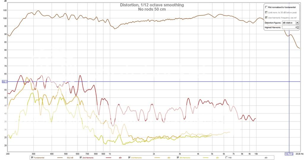
42 rods/no rods at 50 cm (higher couple of traces) and at 200 cm (lower couple of traces):

Distortion, no rods at 50 cm:
42 rods at 50 cm:

I have, as you probably know, no back pole pieces.
This should mean higher distortion levels due to a more non linear flux density.
But it really means a lower total distortion as there is no reflected back wave.
So why not test some back pole pieces while I am at it.
Common threaded rod, diameter 3 mm, about one for each front pole piece:
FEMM simulation showed significant higher flux density, but in reality it only meant 1 dB. No added distortion though.
42 rods/no rods at 50 cm (higher couple of traces) and at 200 cm (lower couple of traces):
Distortion, no rods at 50 cm:
42 rods at 50 cm:
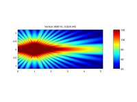
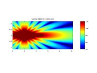
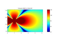
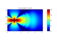
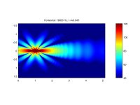
Here's an example of simulation of vertical and horizontal dispersion patterns at 2400 Hz for the 32x4,5 cm AMT:

The AMT source can be seen as a black dotted line around one meter from the front wall to the left.
Sweetspot is a small white dot at 4 meters.
No reflections from the walls, ceiling or floor are considered, neither is any baffle.
The AMT source can be seen as a black dotted line around one meter from the front wall to the left.
Sweetspot is a small white dot at 4 meters.
No reflections from the walls, ceiling or floor are considered, neither is any baffle.
Last edited:
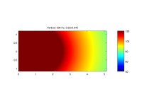
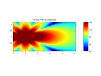
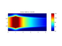
Vertical dispersion patterns for the 32x4,5 cm AMT.
Source and sweetspot are according to above; couldn't them into the file.
Source and sweetspot are according to above; couldn't them into the file.
Attachments
-
 V 0.32x0.045 300 Hz.jpg38.4 KB · Views: 80
 -
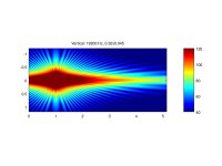 V 0.32x0.045 19200 Hz.jpg69.7 KB · Views: 79
 -
 V 0.32x0.045 9600 Hz.jpg64.8 KB · Views: 74
 -
 V 0.32x0.045 4800 Hz.jpg55.5 KB · Views: 80
 -
 V 0.32x0.045 2400 Hz.jpg48.3 KB · Views: 81
 -
 V 0.32x0.045 1200 Hz.jpg43.1 KB · Views: 71
 -
 V 0.32x0.045 600 Hz.jpg38.7 KB · Views: 71
Last edited:
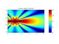
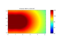
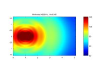
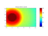
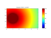
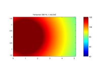
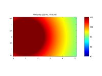
Horisontal dispersion patterns for the 32x4,5 cm AMT.
Attachments
-
 H 0.32x0.045 19200 Hz.jpg65.8 KB · Views: 80
 -
 H 0.32x0.045 9600 Hz.jpg56.5 KB · Views: 76
 -
 H 0.32x0.045 4800 Hz.jpg45.1 KB · Views: 73
 -
 H 0.32x0.045 2400 Hz.jpg43.2 KB · Views: 71
 -
 H 0.32x0.045 1200 Hz.jpg42.7 KB · Views: 62
 -
 H 0.32x0.045 600 Hz.jpg42.5 KB · Views: 69
 -
 H 0.32x0.045 300 Hz.jpg42.5 KB · Views: 73
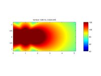
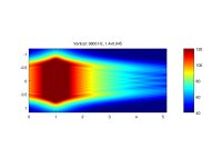
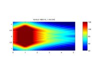
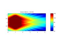
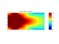
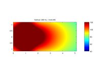
Vertical dispersion patterns for a 140x4,5 cm AMT.
Attachments
-
 V 1.4x0.045 19200 Hz.jpg51.9 KB · Views: 68
 -
 V 1.4x0.045 9600 Hz.jpg52.9 KB · Views: 69
 -
 V 1.4x0.045 4800 Hz.jpg50.9 KB · Views: 67
 -
 V 1.4x0.045 2400 Hz.jpg47.5 KB · Views: 72
 -
 V 1.4x0.045 1200 Hz.jpg44.6 KB · Views: 72
 -
 V 1.4x0.045 600 Hz.jpg42.3 KB · Views: 75
 -
 V 1.4x0.045 300 Hz.jpg39.8 KB · Views: 80
Horizontal dispersion patterns for the 32x4,5 cm AMT.
Attachments
-
 H 1.4x0.045 9600 Hz.jpg55 KB · Views: 69
 -
 H 1.4x0.045 4800 Hz.jpg49 KB · Views: 71
 -
 H 1.4x0.045 2400 Hz.jpg45.2 KB · Views: 65
 -
 H 1.4x0.045 1200 Hz.jpg44.6 KB · Views: 69
 -
 H 1.4x0.045 600 Hz.jpg42.8 KB · Views: 72
 -
 H 1.4x0.045 300 Hz.jpg42.5 KB · Views: 77
 -
 H 1.4x0.045 19200 Hz.jpg53.5 KB · Views: 76
- Status
- Not open for further replies.
- Home
- Loudspeakers
- Planars & Exotics
- Yet another DIY AMT