REW recognizes the UMIK-1 and asks for calibration file. The file includes a Sense Factor so all readings are at correct SPL. No need for an external SPL meter that is!Nice dude !!! Good information . You say umik is standard calibrated for rew ?there is still a mixer/record level for the thing. Where does it supposed to be all depends on the smolifier ofc so what I'd calibrated.
I do not know what "smolifier ofc" means.
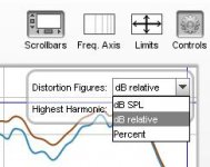
I prefer dBr.How come you rew does not display percentages of distortion ?
I actually got a cold right now, but haven't checked the AMT. How do I know do that?Btw ur amt is sick !! Nice it goes soooo low.
It is a hobby. Others buy Golf Head covers, I buy magnets.One thing to the amount of magnets get pretty expensive
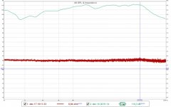
Do you mean in the HF?Looking good. One idea could be to up the resolution drastically on the impedance measurement so that you can see any bump and wiggle as these represent some mechanical deficiency.
//
I am afraid it only noise there:
Good idea. I guess I could at least put some "wind shield" around the AMT.This method has the good thing to leave a mic out of the process. Still, see to that you have silence and do it at night because the measured system will be one giant microphone 🙂
//
Attachments
Attachments
Do you mean in the HF?
No not in frequency but in level. Set the same view as you displayed but make the y-axis cover something like just a few dB so you see all level details under microscope. Check all frequencies, not only HF. You have some bigger bumps at 340 and 440 Hz.
No not in frequency but in level. Set the same view as you displayed but make the y-axis cover something like just a few dB so you see all level details under microscope. Check all frequencies, not only HF. You have some bigger bumps at 340 and 440 Hz.
Sorry, I don't understand. Doesn't post #597 show that already?
Last edited:
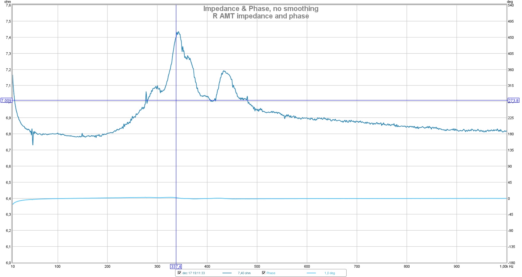
OK - if your trace is that clean from 600 Hz and up your good to go 😉
Your mechanical system see in really good shape except for the problem area around 227 and 420!
Are these membrane or motor/chassis do you think?
//
Your mechanical system see in really good shape except for the problem area around 227 and 420!
Are these membrane or motor/chassis do you think?
//
I don't know really. According to the SPL diagram, the response drops 18 dB an octave below the fs resonance at 360 Hz. At 360 Hz there's also a higher 2nd HD level as well.
If I only could add a weight on the membrane I'd get proper TS parameters...
Now I guess I will have to make more membranes with slightly different layout/suspension in order to figure it out.
Perhaps I will have a go at making a membrane with 2 mm wide pockets and/or deeper than 6,5 mm pockets.
Or I might buy me some Golf Head covers. But that would be really silly as I don't play golf let alone own any golf clubs.
I made some measurements of impedance versus depth of "pockets"
http://origin.dastatic.com/forums/gallery/data/1954/res_freq_div.JPG
More pictureshttp://www.diyaudio.com/forums/planars-exotics/218549-diy-amt-48.html
Weight is added due more alu in the trace
Bernt
http://origin.dastatic.com/forums/gallery/data/1954/res_freq_div.JPG
More pictureshttp://www.diyaudio.com/forums/planars-exotics/218549-diy-amt-48.html
Weight is added due more alu in the trace
Bernt
Last edited:

Yeah, I remember that one. Thanks Bernt for the reminder.
So my membrane's pockets being 6,5 mm deep and 320 mm high could fit in as more or less the tables' 7 mm and 160 height.
The videos have started me thinking about the different modes of the AMT and possible source of distortion.
I'll keep you posted.
BTW. I have to check my measurement amplifier too..
Yes, it is always good to reassess.
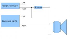
BTW, as I use REW for impedance measurement it very easy, I just use my old EMU 0202 with a headphone output.

(Picture from the above link)
I can determine the 100 ohm Rsense resistor resistance with enough accuracy.
(Picture from the above link)
I can determine the 100 ohm Rsense resistor resistance with enough accuracy.
Attachments
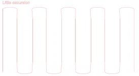
Different modes of an AMT membrane
Top view of an AMT. Here it is a little narrower to make the drawing easier.
Side walls are attached to the frame and cannot move.
Assuming that the foil (4,5 mm wide) is rigid, its suspension consists of the bare 1 mm mylar on each side and the fold.
The fold is 1,6 mm but 1,5 mm wide.
Theoretically that is.

So what happens at a little excursion?

I think that only the sides moves, the folds are intact; the side/fold acts like a hinge.
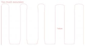
More excursion:

Now also the folds are deformed but the membrane is still within linear limits.
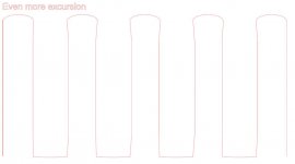
So even more:

Now the suspension is not enough: the whole membrane moves to one side and the Lorentz' force of a single fold is smaller than the combined force of several folds.
I think this sets the fs as the output is now less and for sure there are a high level of distortion as well as the membrane is not behaving linear any more.
Thoughts anyone? Other theories?
Top view of an AMT. Here it is a little narrower to make the drawing easier.
Side walls are attached to the frame and cannot move.
Assuming that the foil (4,5 mm wide) is rigid, its suspension consists of the bare 1 mm mylar on each side and the fold.
The fold is 1,6 mm but 1,5 mm wide.
Theoretically that is.
So what happens at a little excursion?
I think that only the sides moves, the folds are intact; the side/fold acts like a hinge.
More excursion:
Now also the folds are deformed but the membrane is still within linear limits.
So even more:
Now the suspension is not enough: the whole membrane moves to one side and the Lorentz' force of a single fold is smaller than the combined force of several folds.
I think this sets the fs as the output is now less and for sure there are a high level of distortion as well as the membrane is not behaving linear any more.
Thoughts anyone? Other theories?
Attachments

One more thing re impedance measurement.. In order to see mechanical wiggles one have to measure at relevant sound pressure.. the headphone output might not do.
//
//
Turns out that the folding tool for 2 mm wide and 10 mm deep pockets are really easy to put together.Now I guess I will have to make more membranes with slightly different layout/suspension in order to figure it out.
Perhaps I will have a go at making a membrane with 2 mm wide pockets and/or deeper than 6,5 mm pockets.
Just anodized aluminium bars 2 mm thick and 15 and 25 mm wide in a 40 mm wide tool.
First layer of 15+25 mm to the left and second to the right and so on.
One more thing re impedance measurement.. In order to see mechanical wiggles one have to measure at relevant sound pressure.. the headphone output might not do.
//
yes putting a power amp in between with voltage devider makes all more complicated but , i tried the method as described here for TS measurements and outcomes where a bit random. a power amp is probable needed fot this measurements as well 🙁
Yes of course.One more thing re impedance measurement.. In order to see mechanical wiggles one have to measure at relevant sound pressure.. the headphone output might not do.
//
Need to have a much lower resistance then. The resistor has to be 20 W or so in order not to have thermal compression in the resistor.
Could be hard to come by with the needed accuracy.
What type of resistor are you using?
yes putting a power amp in between with voltage devider makes all more complicated but , i tried the method as described here for TS measurements and outcomes where a bit random. a power amp is probable needed fot this measurements as well 🙁
Yes of course.
The idea here was to use the inherent method in REW though.
- Status
- Not open for further replies.
- Home
- Loudspeakers
- Planars & Exotics
- Yet another DIY AMT