I think you have to give same voltage to Q26/27 so in mine opinion 2SJ103 is more appropriate device, lower capacitance comes with it also.
Indeed, 2SJ103 (blue) is better, though not because of equal Vce of Q26/27 (they were already equal), rather higher Vce.
Also J2 should be selected with some care in order to get equal Vce of Q3/4.
C.E.
Also J2 should be selected with some care in order to get equal Vce of Q3/4.
C.E.
You might want to think about the 3 stage output driver, you can get some pretty good discrete transistors, like the Zetex high current high hfe parts, in the real world of discrete you don't need to worry about that their dies probably are bigger than your usual total integrated opamp die size budget 🙂
I would still say that my single stage output driver gives great results, but try with a two stages with final stage Zetex parts and see what happens....
And maybe the LED bias I use, it's nice with a little red glow 🙂, all those fets need matching/selection in the real world.
Then you might get close to something that can fit 10x10mm....
http://www.diyaudio.com/forums/solid-state/156674-my-take-buildable-discrete-op-amp.html
Søren
Also J2 should be selected with some care in order to get equal Vce of Q3/4.
It's mission imposible i think (as a non EE😀), best one can do is to place another pnp Q, base to gnd, in the current mirror input leg.
two stages OPS
I tried that with high gain trannies. Not a good idea. Much more distortion.
C. E.
[snip]
but try with a two stages with final stage Zetex parts and see what happens....
[snip]
Søren
I tried that with high gain trannies. Not a good idea. Much more distortion.
C. E.
What I would do is dispense all J-fets in VAS current tunnel (sorry Scott) and use Hawksford cascode on current mirror output side.
Also, I would use bootstrapped cascode over input J-fets, resistor (10xR11) from Q26/27 base to cascode Q base, another resistor (10xR9) from output to cascode Q base, and finally 100u elcap from cascode Qs base to J1 drain...Now look haw THD looks like ;-)
Last edited:
cascode

Or a Dimitri cascode.
Dimitri Danyuk, “On the Optimization of Enhanced Cascode,” Preprint #7571, Presented at the 125th AES Convention, October 2–5, 2008 San Francisco, CA, USA.
What I would do is dispense all J-fets in VAS current tunnel (sorry Scott) and use Hawksford cascode on current mirror output side.
Or a Dimitri cascode.
Dimitri Danyuk, “On the Optimization of Enhanced Cascode,” Preprint #7571, Presented at the 125th AES Convention, October 2–5, 2008 San Francisco, CA, USA.
Edmond,
If you have that article in mailable form, may I have it please? I am aware of Dimitri's work, but I can't remember right now what that cascode looks like.
If you have that article in mailable form, may I have it please? I am aware of Dimitri's work, but I can't remember right now what that cascode looks like.
Good to see some lively discussion, I have not seen Dimitri's article either. Also if anyone want's to post some schematics of actual changes that would be fun. I would gladly try and optimize another approach/use better devices as an educational exercise. Remember sub-PPM distortions is the stuff of simulators
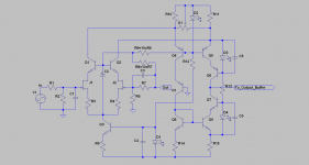
The goal was to see what could be done with a single gain stage and buffer. The Aol looks to be 10^6 which is about a 10^8 Ohm DC impedance at the gain node. For distortion of course the dynamic impedance and its symmetry matter more. It's pretty decent for 23 devices.
I was hoping to try two little verticle cards in a DIP form factor not try and get something into 10mm square though a stack with through pins might work.
The extra circuitry makes it more difficult especially bypassing bias nodes.
Last edited:
Before we go on adnauseum, the reclaiming of base current in a cascode is not new. Bipolar realizations use more stuff especially in some caes coupling capacitors, the FET's actually use less.
A quick read shows 20dB improvement on the Hawksford and I saw 23dB on the FETs, probably a wash in a real circuit.
A quick read shows 20dB improvement on the Hawksford and I saw 23dB on the FETs, probably a wash in a real circuit.
What I would do is dispense all J-fets in VAS current tunnel (sorry Scott) and use Hawksford cascode on current mirror output side.
Could you elaborate? Losing the upper cascode ruins the distortion even putting a perfect mirror (ideal controlled sources) on the bottom.
The input cascode still might help at low gains (non-inverting). I might try an ideal cascode tonight and see.
i whould use a resistor in series with the LED to drive the base and separating the bias arangement.
scott i am really surprised that you know the artwork of Beuys one of our most influential sculptours after world war 2. he came up with the idea to use human beings as art.
scott i am really surprised that you know the artwork of Beuys one of our most influential sculptours after world war 2. he came up with the idea to use human beings as art.
I'm full of surprises. We have a large permanent installation here at Mass MOCA. My wife's first husband knew Beuys while stationed in Berlin, purely coincidence. 🙂
The avatar OTOH is Kurt (my dada hero).
- Status
- Not open for further replies.
- Home
- Amplifiers
- Solid State
- Yet another discrete op-amp