
Hi Scott,
Didn't you forget the cascodes at the IPS?
Cheers,
Edmond.
If you match/(use low) source resistance or use inverting config. there is not much harm. The drain voltages don't move much so there is no Miller. I suppose a good bet would be to tie some highish Vp JFETS to the sources of the input transistors so as not to add much stuff.
ikoflexer - For one with the right parts you could do +-30V supplies, your IC selection there is very limited. On another practical point a discrete design has access to all internal nodes and can have FR /compensation tailored to the application, now your choices are even more limited.
There's room for all approaches, chipamps, T-amps, etc.
Last edited:
One comment, this first gen is aimed at 20dB+ applications. There is more work needed for low gain circuits. The distortion cancellation is less of a factor when the input signals are large and things like common mode linearity are a factor. A more conventional topology might be adequate there.
If you match/(use low) source resistance or use inverting config. there is not much harm. The drain voltages don't move much so there is no Miller. I suppose a good bet would be to tie some highish Vp JFETS to the sources of the input transistors so as not to add much stuff.
[snip]
How much is 'much'?
Besides, to me it makes little sense to use a primitive input stage together with a highly sophisticated/optimized VAS and OPS.
In the meantime I will simulate are your circuit with and without cascodes and let you know about the outcome.
Cheers,
Edmond.
How much is 'much'?
Besides, to me it makes little sense to use a primitive input stage together with a highly sophisticated/optimized VAS and OPS.
Scott has obviously an IC mindset 😀. What may look primitive in a discrete design could be ultra high performance on a chip (due to matching).
In this design, I would be more concerned about the common mode distortions in non inverting configuration, rather than the cascoding impact.
Scott has obviously an IC mindset 😀. What may look primitive in a discrete design could be ultra high performance on a chip (due to matching).
In this design, I would be more concerned about the common mode distortions in non inverting configuration, rather than the cascoding impact.
That's my concern too (i.e. common mode distortion).
Hence my question about cascoding.
Scott, one more question: how large is the tail current of the IPS?
C.E.
2.5mA is where I started and the whole thing runs on 20-25mA. Considering that in actual use there might be a variable source R control on the input the cascode could be a good idea. OTOH there is probably a suitable FET with <10pF Cgd. I suspect a lot of the FET "rolling" that microphone modders do is due to Cgd issues.
It is a fair question, I need to actually get it working (and stable 🙂 ) on the bench to check it out.
Hi Scott,
I was starting with 2.0mA. So almost the same current.
In the meantime I did some THD sims:
f = 20kHz, Acl = 20dB, Vo = 10Vpp, BW = 200kHz, Rl = 1k and Ri is the source imp. of the signal source.
If Ri = 0 -> THD20 = 1.87ppm
If Ri = 1k -> THD20 = 6.44ppm (courtesy of Mr Miller)
Next I inserted the cascodes:
If Ri = 0 -> THD20 = 1.79ppm
If Ri = 1k -> THD20 = 1.81ppm
As you see (and predicted by you) at low source impedances there is not much benefit of adding cascodes.
However, at 1k and above, it makes all the differences.
C. E.
PS: You have mail.
Scott, could you please share with us the spice model you used for the 2SK170?
There are several models doing the rounds out there and the parameters vary considerably.
I have simed your design using multisim (I have LT Spice and sometimes use it but the GUI etc is SO much more friendly in multisim!) and now have it working and compensated. It seems very impressive so far.... the problem I'm having is that if I set IPS tail current to any more than about 2mA the whole thing sits there saturated against the positive rail 🙁 optimum results seem to be with around 1mA but this must be having other knock on effects... output bias not the least...)
2SK117 gives much better results in multisim and I can at least get the OPS quiescent current about right. Comparing the model of the 2SK170 in multisim with the one I have in LT spice (can't remember where I got it from) they are quite different. The BJTs are identical.
BTW. what values of compensation cap/s did you settle on in your own sims for 20dB gain?
Jez.
Pretty basic model, it does not matter that much because SPICE does not have a good short channel FET model so the final say is in the build anyway.
.model 2sk170 njf &
vto = -.556,beta = .022,lambda = 11.5e-3,cgs = 30.0pf,cgd = 30.0pf,pb = .6,mjd = .5,mjs = .5
I was trying around 22-27pF. Sorry about the latch-up, the current mirror needs a clamp diode (usually just an extra emitter which discretes don't have 🙂 ). Again, I was initially motivated by high gain preamp applications where the crossover can kill 'ya. Even the JE990 is only -64dB THD or worse there.
I'll find an easy clamp this weekend.
[snip]
the problem I'm having is that if I set IPS tail current to any more than about 2mA the whole thing sits there saturated against the positive rail
[snip]
Jez.
Hi Jez.
I encountered the same problem (using models of MC9), but I though it was a typical a quirk of my simulator. Therefore I decided to not bother Scott with this (minor???) issue.
C.E.
Yes, I feel obliged to fix that 🙂 . It's related to the old op-amp phase reversal problem. I'll play tomorrow (or tonight) it's cold and dreary here anyway.
Yes Mr Stuart, I see no indication of your sig line being a moderator policy, as requested.
Thank you.
Thank you.
latch-up
Hi Scott,
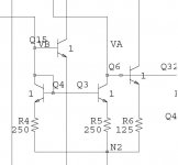
If you don't mind, I think the latch-up originates from something else. If I increased Ic of Q11 by doubling the emitter area and/or decreasing R7, the latch-up has gone.
Ic-Q11 should be equal to Ie-Q3 + ie-Q4 + a sufficient margin.
C. E.
Yes, I feel obliged to fix that 🙂 . It's related to the old op-amp phase reversal problem. I'll play tomorrow (or tonight) it's cold and dreary here anyway.
Hi Scott,
If you don't mind, I think the latch-up originates from something else. If I increased Ic of Q11 by doubling the emitter area and/or decreasing R7, the latch-up has gone.
Ic-Q11 should be equal to Ie-Q3 + ie-Q4 + a sufficient margin.
C. E.
Sorry guyS
I think the latch-up originates mainly with my choice of using a fortuitous connection of Q15. I wanted to balance by symmetry the collector loads and thought I could get base drive for free on Q4 and Q3. Q15 can overdrive the mirror and invert the phase. This connection (I think) eliminates the effect. This weekend i worked out a pretty good conventional single stage amp with some good performance. Next post.
Thanks Edmond for keeping me on my toes, BTW.
Attachments
Last edited:
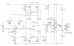
OK here is a more conventional Wilson/Widlar telescoped cascode stage but with FET's. It turns out the connection shown recycles the displacement current in the Cgd's and gets -118dB at 20V p-p into 100 Ohms worst case harmonic @1kHz.
syn08 is right I err on the side of doing IC design, I think this is more in line with what you can do with a full spectrum of components.
syn08 is right I err on the side of doing IC design, I think this is more in line with what you can do with a full spectrum of components.
Attachments
Last edited:
- Status
- Not open for further replies.
- Home
- Amplifiers
- Solid State
- Yet another discrete op-amp