have you guys ever tried tubes as css and tube heaters?
I did a few circuits with Pentodes in the past. They were tedious, noisy and perhaps a bit unpredictable. They also required space, sockets, heater volts, etc.
The first circuits I built with IXCP10M45S and LM317 cascaded CCS were far superior.
Ian
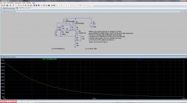
With a better mathematical model from here
http://www.diyaudio.com/forums/soft...-power-mosfet-models-ltspice.html#post4158594
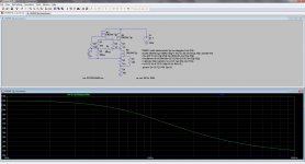
DN2540 cascode worsen significatively at 100mA
Yes, with that model performance even with the Walt Jung bias deteriorates after about 85mA.
However, you could still use two of these cascodes in parallel. At 50mA I am getting impedance of 15Meg for 20KHz.
Its probably too much of a bother, but maybe not? Do you need this for each channel? Also, the upper 'FET needs to dissipate over 7 Watts in such a cascode so keeping it cool will be a consideration.
Or maybe your last schematic will be easier to build...
ian
Last edited:
Yes, with that model performance even with the Walt Jung bias deteriorates after about 85mA.
However, you could still use two of these cascodes in parallel. At 50mA I am getting impedance of 15Meg for 20KHz.
Its probably too much of a bother, but maybe not? Do you need this for each channel? Also, the upper 'FET needs to dissipate over 7 Watts in such a cascode so keeping it cool will be a consideration.
Or maybe your last schematic will be easier to build...
ian
Hi Ian
What about this?


Hi Popilin!
Here's another thought.....
You're designing a shunt regulator, and you want a high performance CCS, so that you get the best possible power-supply rejection ratio. (If that's not your goal, please ignore the rest of the post).
The modelling you have shown (post № 37, for example) shows 80dB or more of rejection into a load of 100Ω.
But if you build a reasonably good shunt regulator - with a compound PNP + N-channel output transistor, the rejection will be much better than 80dB - in fact it will be better than 100dB based on the same modelling. This is because the Shunt part of the regulator will achieve a dynamic impedance of much lower than 100Ω. Probably, much better than 1Ω.
If you are still following my argument, then my design-suggestion is:
1. Use a single DN2540 CCS. If more power handling is needed, use a cascoded PNP and P-channel FET as CCS.
2. Use a Shunt Regulator design with compound output stage (e.g. PNP-N-ch., like the SSHV does).
3. Build it, and measure the real-world PSRR.
4. If PSRR is not good enough for your design goal, add a N-channel capacitor-multiplier in the raw dc line. These are easy to build, and N-channel FETs with high power handling are cheap.
The end result of this design should easily reach 100dB of PSRR. At low frequency, 120dB may be possible. Trying to achieve higher than this is probably a waste of time in a valve/tube circuit, because the large size of all the components and wiring will always allow electromagnetic coupling from the raw dc. This means that you will probably never exceed 100dB of rejection in practice, especially at higher frequencies.
It will be much easier to build than using multiple cascode, with high-impedance bias networks etc. But the real-world performance will be at least as good, without the complicated construction!
4. If PSRR is not good enough for your design goal, add a N-channel capacitor-multiplier in the raw dc line. These are easy to build, and N-channel FETs with high power handling are cheap.
Hello Rod,
Could you post schematic or link.
TIA
Felipe
You posted a schematic for a mosfet cap multiplier yourself a couple of days ago.Hello Rod,
Could you post schematic or link.
TIA
Felipe
Here's another thought..... <snip>
Hi Rod
Thank you very much for so wise advise!
I think that my design fulfilled all your mentioned points in terms of PSRR, however in my ignorance, I have not a clue about how much isolation between raw supply and shunt regulator is needed just to avoid that audio signal return current pass through raw supply (and/or rectifiers).
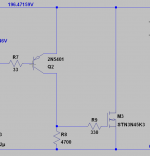
You posted a schematic for a mosfet cap multiplier yourself a couple of days ago.
That's not mine, it's DHTRob schematic, I need only the cap multiplier section.
I don't get it. Just use the cap multiplier section and adjust the component values to your needs.That's not mine, it's DHTRob schematic, I need only the cap multiplier section.
That's not mine, it's DHTRob schematic, I need only the cap multiplier section.
The IRF830, and the parts connected to it.
Hi Popilin!
You'd have to build and measure to get an accurate assessment, but we can estimate the value, with some approximations.
Shunt Regulator with dynamic impedance of <100mΩ should not present any problems to design and build, and you may get much better than this, using the PNP-N-channel compound output stage.
Your design has a 100mA standing current, so if you have a class-A SE power amp as a load, the zero→peak current might be 40mA. At 100mΩ, the voltage swing on the supply will be 4mV, zero→peak.
Now let's say we made a fairly bad current source. It has a dynamic impedance of only 100KΩ. If we treat it to the 4mV supply-voltage swing, the resulting leakage current back to the raw dc supply will be:
4e-3/100e3 = 40nA (!)
Naturally, this will have no effect on anything!
OK these are approximations, and you should build and measure. But No reason to think that you need a high performing current source, I suspect. The performance of the shunt regulator will make far more difference, and I would just build a CCS with a P-ch FET like the ONSemi (Fairchild) FQP3P50, and concentrate on the shunt section. This will have more effect on the sound quality.
Hi Popilin!
You'd have to build and measure to get an accurate assessment, but we can estimate the value, with some approximations.
Shunt Regulator with dynamic impedance of <100mΩ should not present any problems to design and build, and you may get much better than this, using the PNP-N-channel compound output stage.
Your design has a 100mA standing current, so if you have a class-A SE power amp as a load, the zero→peak current might be 40mA. At 100mΩ, the voltage swing on the supply will be 4mV, zero→peak.
Now let's say we made a fairly bad current source. It has a dynamic impedance of only 100KΩ. If we treat it to the 4mV supply-voltage swing, the resulting leakage current back to the raw dc supply will be:
4e-3/100e3 = 40nA (!)
Naturally, this will have no effect on anything!
OK these are approximations, and you should build and measure. But No reason to think that you need a high performing current source, I suspect. The performance of the shunt regulator will make far more difference, and I would just build a CCS with a P-ch FET like the ONSemi (Fairchild) FQP3P50, and concentrate on the shunt section. This will have more effect on the sound quality.
Hi Rod
Thanks again, you put things very easy to me with those approximations, from now I can calculate more things.
Due to the wrong mathematical model for NE5534, my opamp based shunt regulator is making water, and I cannot obtain a plain output impedance anymore.
As a final effort, can you please post a link to a PNP-N-channel compound output stage?
With a better mathematical model from here
http://www.diyaudio.com/forums/soft...-power-mosfet-models-ltspice.html#post4158594
Something is strange with DN2530 model.
In reality, Supratex-TO92 original model is accurate.
Something is strange with DN2530 model.
In reality, Supratex-TO92 original model is accurate.
DN2540 subthreshold model clearly gives more accurate simulations as they are closer to some measurements, however I have not a clue about DN2530.
- Status
- Not open for further replies.
- Home
- Amplifiers
- Tubes / Valves
- Yet another CCS