Hmmm... Did you ever try a capacitor in your power supply? 🙂
Hi Anatoliy, nice to see you!
Of course I do, but now the idea is isolate raw supply from shunt regulator, so I need a CCS.
Hi Popilin...
Some thoughts:
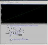
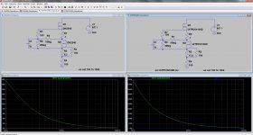
Firstly, the opamp version will not perform as well as it looks. This is partly because of stray capacitance from the main supply to the opamp supply. Think about the capacitance of the mains-transformer windings (P→S), and stray capacitance of the layout. I put 120pF to test it, as a 1st approximation - and you can see how it degrades at high frequency.
See also that I have added frequency compensation for the op-amp (I can't look at uncompensated power-transistor driver-circuits!)
Some thoughts:
Firstly, the opamp version will not perform as well as it looks. This is partly because of stray capacitance from the main supply to the opamp supply. Think about the capacitance of the mains-transformer windings (P→S), and stray capacitance of the layout. I put 120pF to test it, as a 1st approximation - and you can see how it degrades at high frequency.
See also that I have added frequency compensation for the op-amp (I can't look at uncompensated power-transistor driver-circuits!)
Attachments
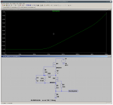
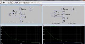
Next, I looked at the DN2540 version, and the problem of achieving a 100mA source. This can be fixed with Walt Jung's bias network, which increases the voltage headroom on the downstairs FET. Now 100mA is easily available, and the supply rejection improves, too.
Maybe the turn-ON power problem can be fixed by using a Alu spreader-bar for the heatsink. Ebay sellers usually have short lengths of thick (5-7mm) Alu - say, 50mm x 100mm, that can absorb thermal pulses at startup.
If that is not enough, you can double-up the upstairs FET, (leave a single below) to get more power handling - at the expense of worse supply-rejection. Or maybe the higher-power IXYS parts will help, but these are harder to obtain, here.
Attachments
Hi Popilin...
Some thoughts:
Firstly, the opamp version will not perform as well as it looks. This is partly because of stray capacitance from the main supply to the opamp supply. Think about the capacitance of the mains-transformer windings (P→S), and stray capacitance of the layout. I put 120pF to test it, as a 1st approximation - and you can see how it degrades at high frequency.
See also that I have added frequency compensation for the op-amp (I can't look at uncompensated power-transistor driver-circuits!)
Hi Rod, nice to see you around here! Thanks a lot for your input!
I always add an electrostatic shield when I wind my transformers, but never think about its consequences on the circuits, bad habit.
I never add a frequency compensation network unless the circuit oscillates, another bad habit or just ignorance, added resistor R5 is mandatory.
Next, I looked at the DN2540 version, and the problem of achieving a 100mA source. This can be fixed with Walt Jung's bias network, which increases the voltage headroom on the downstairs FET. Now 100mA is easily available, and the supply rejection improves, too.
Maybe the turn-ON power problem can be fixed by using a Alu spreader-bar for the heatsink. Ebay sellers usually have short lengths of thick (5-7mm) Alu - say, 50mm x 100mm, that can absorb thermal pulses at startup.
If that is not enough, you can double-up the upstairs FET, (leave a single below) to get more power handling - at the expense of worse supply-rejection. Or maybe the higher-power IXYS parts will help, but these are harder to obtain, here.
It is not a heatsink problem, I can calculate and make it properly, the issue is that the shunt regulator has a soft start and push the CCS to dissipate about 30W for some seconds at turn-on, this is easy for the IRF830, but for the DN2540 I must add a pre-regulator with the soft start there.
FYI:
Hi Merlin, thanks for your input.
It looks like models are optimistic, at 10mA sims are something like this
Attachments


yes.
enjoy
Code:
* PSpice Model Editor - Version 9.2.1
*$
.SUBCKT IXTP01N100D D G S
*********************************************************************
*Note:                                                              *
* Althought models can be a useful tool in evaluating device        *
* performance, they cannot model exact device performance           *
* under all conditions, nor are they intended to replace            *
* bread boarding for final verification. Therefore IXYS does        *
* not assume any liability arsing from their use.  IXYS reserves    *
* the right to change models without prior notice. The Pspice model *
* does not constitute product data sheet. Designer should refer to  *
* the data sheet to guranteed the limit and specification.          *
*********************************************************************
** model generated on Jan 14, 2013
* Node 1 -> Drain
* Node 2 -> Gate
* Node 3 -> Source
M110 D G S1 S1 MM111
L_s S S1 1n
.MODEL MM111 NMOS
+ LEVEL=3
+ L=2.0000E-6
+ W=.4
+ KP=1.0431E-6
+ RS=10.000E-3
+ RD=49.597
+ VTO=-2.2067
+ RDS=1.0000E9
+ TOX=2.0000E-6
+ CGSO=25.000E-15
+ CGDO=1.9992E-12
+ CBD=105.33E-12
+ MJ=1.0378
+ PB=1.6953
+ RG=10.000E-3
+ RB=1.0000E-3
+ GAMMA=0
+ KAPPA=0
*
L_bd S2 S 1n
D_1 S2 D BD
.MODEL BD D
+ IS=626.27E-9
+ N=2.3975
+ RS=1.0000E-3
+ CJO=106.80E-12
+ M=1.1185
+ VJ=1.6503
+ ISR=1.0588E-9
+ BV=1.0001E3
+ IBV=2.6125
+ TT=270.51E-9
.ENDS
*$Hidden issue here (mostly when you want put into hi impedance anode area) is the parasitic capacitance of support circuitry to supply lines.As I need a 100mA CCS, mathematical models from Supertex does not help, so looking for another solution, I found
You probably would use something like TRACO bricks instead that floating DC supply icon. Or even separate trafo winding +rectifier has also capacitance to neighbour windings. hum,buzz..
Simulation IMHO does not take such hidden parasitics into consideration.
This problem is like drawing xx-xxx pF across that floating supply to gnd.
Product detail view | tracopower.com
20pF@100kHz= ~80k
Tiny battery, with short wires and away from circuit could minimize parasitics, not easy to do
Last edited:
maybe the higher-power IXYS parts will help, but these are harder to obtain, here.
I ordered a few IXTP01N100D through mouser in my last order, but I admit that they are costly in comparison to DN2540. I also took the time to order some decent sized Aavid Thermalloy heat sinks from mouser, which I am very happy with as well. Mouser delivers to Switzerland - so maybe they deliver to the UK as well. My experience with them has been quite positive.
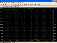
Its interesting comparing simulated "standard" cascodes of IXTP01N100D vs. DN2540 - up to about 25mA the IXYS part gives stellar performance, but then 20KHz performance dramatically falls off. The "standard" cascoded DN2540 can handle up to about 50mA before the 20KHz performance rapidly deteriorates.
One simple solution might be doubling the cascode of DN2540... but I must admit that the Walt Jung bias solution clearly gives better performer for both Parts, and if the upper 'FET needs to dissipate a lot, then doubling it up is always possible.
Attached are simulations of both parts using the Walt Jung bias. @20KHz for DN2540 is still better than 1Meg, while for the IXYS part its something over 25Meg. You can also combine the two 😉
Attachments
Last edited:
Hidden issue here (mostly when you want put into hi impedance anode area) is the parasitic capacitance of support circuitry to supply lines.
You probably would use something like TRACO bricks instead that floating DC supply icon. Or even separate trafo winding +rectifier has also capacitance to neighbour windings. hum,buzz..
Simulation IMHO does not take such hidden parasitics into consideration.
This problem is like drawing xx-xxx pF across that floating supply to gnd.
Product detail view | tracopower.com
20pF@100kHz= ~80k
Tiny battery, with short wires and away from circuit could minimize parasitics, not easy to do
Hi hpeter, thanks for your input.
Another alternative, a statistical regulator "a la Morgan Jones"


Its interesting comparing simulated "standard" cascodes of IXTP01N100D vs. DN2540 - up to about 25mA the IXYS part gives stellar performance, but then 20KHz performance dramatically falls off. The "standard" cascoded DN2540 can handle up to about 50mA before the 20KHz performance rapidly deteriorates.
With a better mathematical model from here
http://www.diyaudio.com/forums/soft...-power-mosfet-models-ltspice.html#post4158594
DN2540 cascode worsen significatively at 100mA


I ordered a few IXTP01N100D through mouser in my last order, but I admit that they are costly in comparison to DN2540.
You could ask Kevin from "K&K audio" for ixtp/dn price.
You could ask Kevin from "K&K audio" for ixtp/dn price.
Perhaps useful advice for some other DIY'er looking for a few pieces. Hope you enjoy the model. All I had to do was ask IXYS for it... 😉
- Status
- Not open for further replies.
- Home
- Amplifiers
- Tubes / Valves
- Yet another CCS