Hi Piersma.
You are right. The frontend will be regulated, at least it will have an RC filter wich is not presented in the simulation.
As you point out.. It is a problem with current feedback.
You are right. The frontend will be regulated, at least it will have an RC filter wich is not presented in the simulation.
As you point out.. It is a problem with current feedback.
hi Sonnya,
Nice circuit that will provide nice THD figures.
Did you check the PSRR?
By nature the current feedback configuration results in a poor PSRR.
I would run the front end from a regulated supply.
regards,
Piersma
The PSRR from either rail is 41dB.
I have made an linear regulator for the frontstage. It has 64dB rejection onto it.
So PSRR is now up to >100dB.
I could do that. The amplifier has a flat PSRR of 41dB from 0 - ~6KHz.
If you make an RC filter, the low region of the frequence spectre does not has a big improvement. I could use an RC filter like the one you have described in you own thread (33R + 1000uF) but a active discrete regulator costs the same and will provide aditional 63dB from 0 - 10KHz. Afterwards it will only get better.
it consists of 7 transistors per rail for 0,5DKK per transistor.
Last edited:
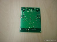
pcb layout.
Okay, i have done the layout.
as you can see i have attached it.
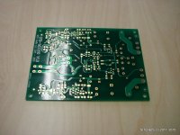
It looks complex but you can actually see that it has building blocks.
The center of the pcb is where you have the amp itself. with powersupply and regulator running down the side of the board.
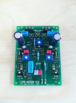
In front you have the input. I have decided to add a servo from my Mirand A1 design as the amp will drift 100mV over temperatur from 0 - 80 degrees celcius.
The integrator is made with an PHE426 capacitor from evox rifa.
The feedback network is CMF55 from vishay/dale. They are 25ppm 0.1% So they are quite stable.
This amp is fully scalable up and down.
I have for fun changed the output mosfet to ZVN/ZVP3310 + 10R degeneration, added ccomp of 2 x 33pF, Lowered the rails to +/-25V,changed the gain to ~4xgain (1k+330R feedback network).
In this configuration it performs extremely well. We are talking distortion figures of 0.004% at 10Vrms into 1K load at 1KHz. at 1Vrms it is down to 0.0003%
Okay, i have done the layout.
as you can see i have attached it.
It looks complex but you can actually see that it has building blocks.
The center of the pcb is where you have the amp itself. with powersupply and regulator running down the side of the board.
In front you have the input. I have decided to add a servo from my Mirand A1 design as the amp will drift 100mV over temperatur from 0 - 80 degrees celcius.
The integrator is made with an PHE426 capacitor from evox rifa.
The feedback network is CMF55 from vishay/dale. They are 25ppm 0.1% So they are quite stable.
This amp is fully scalable up and down.
I have for fun changed the output mosfet to ZVN/ZVP3310 + 10R degeneration, added ccomp of 2 x 33pF, Lowered the rails to +/-25V,changed the gain to ~4xgain (1k+330R feedback network).
In this configuration it performs extremely well. We are talking distortion figures of 0.004% at 10Vrms into 1K load at 1KHz. at 1Vrms it is down to 0.0003%
Attachments
Would be fun making layout.
But when I added transistors to library I answered: Simulation only
So, when I transfer to PCB layout I get no devices.
But when I added transistors to library I answered: Simulation only
So, when I transfer to PCB layout I get no devices.
Gate resistors
hi Sonnya,
Great to see you are not only simulating but also building this amplifier like OS always does.
I would defenitely increase the gate resistors, 22E is too low in my opinion.
Good luck!
hi Sonnya,
Great to see you are not only simulating but also building this amplifier like OS always does.
I would defenitely increase the gate resistors, 22E is too low in my opinion.
Good luck!
It is a beautiful schematic and amplifier.
Separate frontend supply just make it even better.
The mirrors keep OLG and GNFB at lower level.
Could be a well sounding amp. And still close to Hifi.
Separate frontend supply just make it even better.
The mirrors keep OLG and GNFB at lower level.
Could be a well sounding amp. And still close to Hifi.
Its Azitech in denmark which has a network in china for the High Q production.
Same as elprint, printline, elcon and so on does.
Same as elprint, printline, elcon and so on does.
Exactly.
If Zin of about 10k is enough and non-inverting topology is preferable, the easiest way to do it with this amp would be like this:
Re: schematic of post#20
I think if you used rush cascodes, you could have equal voltage from base
to base in both push and pull. I mean npn+pnp equal voltage across those
220's (R1 and R2) , which would become 440's keeping the same current...
Then your input impedance would be looking into bases.
And npn+pnp = npn+pnp , hopefully means less input offset.

Hi all.
The amp is now running.
It was necessary to amp 2x33pF miller comp and 100R gate resistor to the gates instead of 22R.
The main voltage regulator is bypassed to give more voltage swing...
The RC filter instead of the voltageregulator is 220R + 22uF .. It could be better, but thats what i have installed right now.
The amp is running at idle = 500mA. => 4watt class A.
There is no background noise with the volume controlled turned down. Only very very little hum 2 cm from the woofer.. Barely noticable..
The is no white noise from the tweeter, so that is good.
The volume is an alps R27K 20KOhm connected to the input.
Even at low volume it plays really deep. lots of details. But i need to listen more..
The powersupply is an 300VA 2x25V + 80.000uF shared between the two channels.
The heatsink is an SK56 100mm, one per channel.
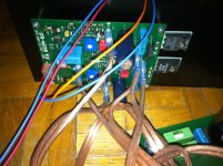
Hi all.
The amp is now running.
It was necessary to amp 2x33pF miller comp and 100R gate resistor to the gates instead of 22R.
The main voltage regulator is bypassed to give more voltage swing...
The RC filter instead of the voltageregulator is 220R + 22uF .. It could be better, but thats what i have installed right now.
The amp is running at idle = 500mA. => 4watt class A.
There is no background noise with the volume controlled turned down. Only very very little hum 2 cm from the woofer.. Barely noticable..
The is no white noise from the tweeter, so that is good.
The volume is an alps R27K 20KOhm connected to the input.
Even at low volume it plays really deep. lots of details. But i need to listen more..
The powersupply is an 300VA 2x25V + 80.000uF shared between the two channels.
The heatsink is an SK56 100mm, one per channel.
Hi Sonny
Congrats 🙂
One of my own DIY PP amp construction, had also a slightly 50 hz hum, but i solved it, with better PS filtering and now it's not noticeable !
+ CRC ( 68000uF - 1 Ohm/50w - 68000uF )
- CRC ( 68000uF - 1 Ohm/50w - 68000uF )
The hum is so low , i expect that the missing enclosure is the answer of this problem..
For fun, i played the sacd sacred love from sting... Earlier this was not one of My favors... But the AMP plays track 5 with more detail than before and track 6 "stolen car" with deep rolling Sound waves..
But right now i cannot decide if it is harsh or not... But track 9 os played very detailed and at the same time the hand drum is very delicate to listen to...
I Think i need more days to see if the AMP is tiring to listen to ...
- Status
- Not open for further replies.
- Home
- Amplifiers
- Solid State
- Yet another amp - simple inverted with 10x gain, mosfet output stage