Let's wait and see what Sonny thinks about changing anything - this is his amp and his thread ...
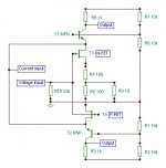
Input impedance.
It's correct if you going to feed it from an passive preamp. Then it's to low.
If you are going to feed it from an preamp or attenuator with an bufferstage. If this buffer is designed the wrong way around then it will be degraded.
As for the construction of using inverted design as this is: The feedback network as is it should be. I would not use higher impedance for LM3886 as well.
National states:
"With the increase in gain, there is
also a reduction of the power bandwidth which results in a
decrease in feedback thus not allowing the amplifier to respond
quickly enough to nonlinearities. This decreased ability
to respond to nonlinearities increases the THD + N specification.
The desired input impedance is set by RIN. Very high values
can cause board layout problems and DC offsets at the
output. The value for the feedback resistance, Rf1, should be
chosen to be a relatively large value (10 kΩ–100 kΩ), andthe other feedback resistance, Ri, is calculated using standard
op amp configuration gain equations. Most audio amplifiers
are designed from the non-inverting amplifier configuration"
This will give a low inputimpedance as well.
But i can follow your point that you want a higher input impedance.
Juma: I have just seen your post.
I did test it yesterday. But because of difference in current gain, you will have with 10k resistor to ground around 500mW on the "in+"
I have drawn an alternative version i will post a bit later.
The reason to post this circuit was that it is symmetrical with low part count to relatively low price.
I have a highperformance circuit but that is not cheap at all.
But i got your points.
I have a highperformance circuit but that is not cheap at all.
But i got your points.
Sonnya
Where do you think DC-offset adjust should be done?
In a mirror perhaps?
I get -126 mV offset in my simulator.
Where do you think DC-offset adjust should be done?
In a mirror perhaps?
I get -126 mV offset in my simulator.
WuYit:
that is okay. Can you get the JFET's as SMT and complementary?
The parts i have choosen besides of the capacitors and mosfet are SMT.
Lineup:
You can get balance in current that is not a big problem. Its more the voltage drop VGS and VBE that will make up the big problem.
My Mirand A1 v11 design uses a servo as i has not added dc blocking capacitors. This one is not cheap and i have a bit more sofisticated circuit on the drawing board.
I wanted to make a cheap symmetrical amp. One way is to use mosfet in the output.
In this one i wanted to remove the DC servo to make i cheap, and i do not think we are getting away without a DC blocking Cap.
In an noninverting design i am down to 33mV at the output with a 4K feedback resistor. But then the step response is not good enough. That i ahve to solve.
You say bias 500 mA. At least.
With 100-200 mA there is higher THD.
This circuit works best in Class A or near full Class A,
where the THD is much lower.
I get a value of THD 0.005% with bias 500 mA.
With 100-200 mA there is higher THD.
This circuit works best in Class A or near full Class A,
where the THD is much lower.
I get a value of THD 0.005% with bias 500 mA.
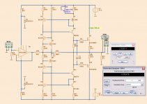
OPA134 + Sonnya Amp
I tried the JFET buffer, but got too much THD (0.037%)
So I added one OPA134 preamp at the input.
Now THD is only 0.004%.
See diagram.
To adjust DC-offset to zero I use one 50k-trimmer (R4)
I used transistors BC550C, BC560C and one 2N5401, 2N5551
I tried the JFET buffer, but got too much THD (0.037%)
So I added one OPA134 preamp at the input.
Now THD is only 0.004%.
See diagram.
To adjust DC-offset to zero I use one 50k-trimmer (R4)
I used transistors BC550C, BC560C and one 2N5401, 2N5551
Attachments

You added the gatestoppers i have forgotten.
The offset-pot i also placed at a good position.
But basicly, this version lineup have made would be easy for all to make even if they have no SMT experience.
The opamp, makes it possible to use an passive preamp section.
Last edited:
modified for noninverted with high input impedance.
Hi WuiYt, Lineup and other.
I have attached the schematic where it is modified for noninverting with an gain of 26.4dB.
Compared to the original schematic it has 3 more resistors and 4 more bjt's.
By adjusting the r6 with an potentiometer offset can be removed as per lineup.
Hi WuiYt, Lineup and other.
I have attached the schematic where it is modified for noninverting with an gain of 26.4dB.
Compared to the original schematic it has 3 more resistors and 4 more bjt's.
By adjusting the r6 with an potentiometer offset can be removed as per lineup.
Attachments
Looks real nice.
Must be very low THD now.
It is now Diamond input. Like Hiraga used in his famous amplifiers.
And Current feedback
Must be very low THD now.
It is now Diamond input. Like Hiraga used in his famous amplifiers.
And Current feedback
2. and 3. is down to 100dB at 1KHz and 1W into 8 Ohm.
2. and 3. is down to 90dB at 1KHz and 10W into 8 Ohm.
Funny enough. They are equal in level.
I talked to my brother this evening, and we wants to build a version with 3 channels on a heatsink.
This HT amp will be running on two cosel L150 SMPS made for medical use. The put out 36V but can be adjusted +/-5V. They can in 10 second give 280W.
He wanted an amp with lower idle current to save on the bill.
The voltage gain stage uses only 6mA.
I am going to make another version also which has powersupply on board like the one SWF and Hugh had made.
Not to copy them. But they actually lead me to use those mosfet, and it turned out that they are easier to get stable than BJT's and need no driverstage for a little amp.
Thanks for getting me to think it over twice
Distortion is at 1W,10W 0.001269% and 0.004907%.
This is at an idle of 1A.
At 150mA idle the thd is up to 10 times higher at 10W. But at 1W the THD is 50 times higher.
At 500mA 10W is still high but 1W is equal to 1A.
To obtain low thd at a relative low idle it is neccesary to use BJT output stage.
This is at an idle of 1A.
At 150mA idle the thd is up to 10 times higher at 10W. But at 1W the THD is 50 times higher.
At 500mA 10W is still high but 1W is equal to 1A.
To obtain low thd at a relative low idle it is neccesary to use BJT output stage.
Hi,
No applause from me.This HT amp will be running on two cosel L150 SMPS made for medical use.
I did not expect it either.
I was just telling about the progress.
Besides if you do not test it, it is unknown land.
I was just telling about the progress.
Besides if you do not test it, it is unknown land.
- Status
- Not open for further replies.
- Home
- Amplifiers
- Solid State
- Yet another amp - simple inverted with 10x gain, mosfet output stage