Yet another adcom GFA-555 debug/refurbish thread
My brother found this at a Salvation Army store for 50 bucks. So far there's one glaring issue - the burnt circuit board on a power supply capacitor (see photos). Dare I even power it up? If I replace the resistor, and something else is an issue, what blows next?
From the threads I've read already, I need to start by pulling the fuses on all 4 amp outputs boards (all 4 are good, so that's a bit of good news). I would imagine with no load, I can use my shiny new Variac to start to power things up. Other than monitoring the capacitor (in case it either took damage in the resistor crisping, or caused it), what else should I be looking for?
Finally, based on the pictures, can anyone comment on which flavor (and therefore circuit diagram & part values) I have?
And regarding my level of experience and available gear: I'm a degreed EE, but have been doing software and digital circuitry for my entire career. I bent circuits fairly regularly and do all kinds of kit builds. I have VOM, oscilloscope, signal generator, semi-pro soldering setup and a dedicated lab bench-let (2'x4').
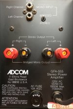
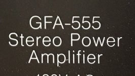
Here is the rear of the amp, including serial number to help ID the unit:

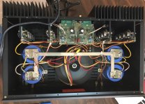
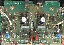
Next is the overall guts, with the only visible damage being the circuit board on top of the cap in the lower right corner:

The final pair of photos are the top & bottom of the damaged board:


My brother found this at a Salvation Army store for 50 bucks. So far there's one glaring issue - the burnt circuit board on a power supply capacitor (see photos). Dare I even power it up? If I replace the resistor, and something else is an issue, what blows next?
From the threads I've read already, I need to start by pulling the fuses on all 4 amp outputs boards (all 4 are good, so that's a bit of good news). I would imagine with no load, I can use my shiny new Variac to start to power things up. Other than monitoring the capacitor (in case it either took damage in the resistor crisping, or caused it), what else should I be looking for?
Finally, based on the pictures, can anyone comment on which flavor (and therefore circuit diagram & part values) I have?
And regarding my level of experience and available gear: I'm a degreed EE, but have been doing software and digital circuitry for my entire career. I bent circuits fairly regularly and do all kinds of kit builds. I have VOM, oscilloscope, signal generator, semi-pro soldering setup and a dedicated lab bench-let (2'x4').
Here is the rear of the amp, including serial number to help ID the unit:
Next is the overall guts, with the only visible damage being the circuit board on top of the cap in the lower right corner:
The final pair of photos are the top & bottom of the damaged board:
Last edited:
Those links are visible but need right click and open in new tab or make them smaller and add them as attachments 
Those links are visible but need right click and open in new tab or make them smaller and add them as attachments
Hopefully that is better now.
They are visible thumbnails now. In general when you will want to attach them as files so they remain no matter what happens to the externally hosted pictures links in the future go advanced reply and there is a manage attachments menu. If you will size them first in something like 1280 horizontal pixels max they get small in kB enough to upload, still good in detail, and they blow up in manageable proportion to the post's frame.
Ok, I give. How do you do what others have done, and get pictures listed as "attached thumbnails"?
I can use the "insert image" button in the posting window, and fill it with links from the Member Galleries. However, the member galleries page gives me 3 options, and the option of "linked thumbnail" is what you see here. In other attempts, I've had little luck in using the other two options presented on the Member Galleries page (Linked Medium and Medium Image), both of which put a large image on the screen and the linked image is the exact same size.
What I'm interested in is thumbnail sized images in the post, but which will get give the larger image when they are clicked on. How is that done?
Like this:
To add a photo, files or non standard files.
First click "go advanced" in the box below the "quick reply" message box. Doesn't matter if you decide half way through a message to do that, it carries it forward.
Then click "Manage attachments". Maximise the new Window so that you can see all the text.
Click browse in the first box at the top and find your picture. Repeat for any more pictures.
Click upload... a message appears "uploading"
When complete the files will show as being attached. Now click the small text that says "close this window"
The pictures should now be attached and when you submit your post they will appear.
Make sure your pics aren't too big, a couple of 100k is plenty, and many members object when they are massive and it alters the margins
It tells you in the attachments window what max sizes are allowed.
If you want to attach a file that has a non standard format for example excel, circuit simulation etc then try putting the files in a zipped folder and attaching that.
Second try, with some minor updates. Many thanks to Salas & Mooly for their help.
-----
My brother found this old Adcom GFA-555 at a Salvation Army store for 50 bucks. So far there's one glaring issue - the burnt circuit board on a power supply capacitor (see photos). Dare I even power it up? If I replace the resistor, and something else is an issue, what blows next?
From the threads I've read already, I need to start by pulling the fuses on all 4 amp outputs boards (all 4 are good, so that's a bit of good news). I would imagine with no load, I can use my shiny new Variac to start to power things up. Other than monitoring the capacitor (in case it either took damage in the resistor crisping, or caused it), what else should I be looking for?
What can I do without it powered, absent a capacitor tester (to verify status of the cap under the cooked board)? Anything with the transformer? The MOV on the isolator strip (beneath main circuit board) looks good, so probably not a power surge?
Finally, based on the pictures, can anyone comment on which flavor (and therefore circuit diagram & part values) I have?
And regarding my level of experience and available gear: I'm a BSEE, but have been doing software and digital circuitry for my entire career. I bend circuits fairly regularly and do all kinds of kit builds. I have VOM, oscilloscope, signal generator, semi-pro soldering setup and a dedicated lab bench-let (2'x4').
Here is the rear of the amp, including serial number to help ID the unit, followed by an interior shot (to help with the ID), and two shots of the crispy capacitor cover circuit board (lower left corner in interior shot):
Attachments
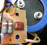
I believe those resistors are "just" old and tired from heat , but still functional
most probably still good enough for powering up , and you can replace them later , hopefully with different physical layout , to give them more air
I believe this (enclosed) is your schmtc , so these resistors are "just" bleeders ...... you can almost go without them
in fact , increasing their value notch up will probably solve overheating issues , while still covering their function
Attachments
Last edited:
Thanks for the quick response, Zen. If I understand you correctly, you believe it may be as simple as the resistor dying of natural causes, and I am simply being paranoid?
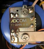
Regarding the enclosed .pdf for a Mk II, it was my understanding from what I had read on these boards that what I had was an actual 555, not a Mk II. Please see the details from the back panel photo and the circuit board photo. I've seen pictures like these before, and was pretty sure the numbers were from one of the flavors of 555, but wasn't sure which one, nor how much difference there was between the various 555 flavors (not including the Mk II).
Any thoughts or ideas?
Attachments
I simply chose GFA-555 schematic which is having complete PSU on it ....... and I believe that part wasn't changed
what outputs your amp is having?
what outputs your amp is having?
Those resistors are metal oxide types, designed for high temperature operation. The board discolouration is a natural process that occurs when it is exposed to long term heat and is perfectly normal. The board and resistors are fine.
I simply chose GFA-555 schematic which is having complete PSU on it ....... and I believe that part wasn't changed
what outputs your amp is having?
Thanks for the power supply schematics, then. 8)
None as yet, haven't plugged it in yet. On my way to donate blood, then play with electronics.
I meant - what output transistors ?
as I can see in schematic - first iteration was with mosfets , while later one was with bipolar transistors
as I can see in schematic - first iteration was with mosfets , while later one was with bipolar transistors
Sorry, Zen, I misunderstood. They're TO-3 packages and one said
Toshiba
2SB554
R '7F
So that should be bipolar.
Toshiba
2SB554
R '7F
So that should be bipolar.
sorry - my bad , mentioning mosfets in first iteration of amp ....... that was - my sore eyes/brain , not clickin' that I clicked on wrong file 
so - again - irrelevant which schematic you're looking at - MKII or not , all is practically the same
if , from some reason , you need exact type schematic , there are many of them floating around
just in case - here's what I have
so - again - irrelevant which schematic you're looking at - MKII or not , all is practically the same
if , from some reason , you need exact type schematic , there are many of them floating around
just in case - here's what I have
Attachments
Last edited:
Update:
Dead simple cap test- ohm meter puts out a little voltage, so I "ohmed out" the capacitors (with the boards still on) and each of them came up to similar readings in similar time intervals. All I was trying to prove was not a dead short, not an open. All behaved similarly. Time for the juice.
With the 4 fuses out of the power-amp boards, I put it on the Variac and slowly brought it up. At 10% steps to 60, then by 5s after that, the voltages across the caps (with almost no load) was within a 1/10th volt. However, using my non-contact pyrometer, the crisped board was at 95 degrees and climbing, so I shut it down after letting it idle at full power (and roughly +/-80v at all 4 caps). The crisped resistor, I imagine, is somewhat lower in resistance, and throwing more heat. Next step is to remove it and try to get a reasonable replacement.
Anything else I should test before putting fuses in the good side for some baseline measurements?
well , if you don't have shortie across PSU rails , that's good for start
you can use bulb tester for first real powering up
you can use bulb tester for first real powering up
also - with 80V rails , you'll have 1W64 across each of 3K9 resistors
so , that's normal to have them crikey hot
however - having them so hot is not normal in my book , so feel free to replace them with double valued ones ...... say 8K2/3W , resulting in 0W8 of heat
so , that's normal to have them crikey hot
however - having them so hot is not normal in my book , so feel free to replace them with double valued ones ...... say 8K2/3W , resulting in 0W8 of heat
delecoy: Welcome. Hope these notes and everything else in the forums help you with your project.
Zen: Have some 8K2 power resistors on the way. And the LED works all the way down to about 8v (power it up, power it down, attach VOM to cap, compare brightness to voltage), so I'm looking at replacing the LED's resistor with a 39K resistor for about the same 2mA as the 3K9 passes at 8v, but at 0.164W, so a quarter watt resistor should work. Or am I missing something about the power rating (do you think that 50% too small a margin?)?
Zen: Have some 8K2 power resistors on the way. And the LED works all the way down to about 8v (power it up, power it down, attach VOM to cap, compare brightness to voltage), so I'm looking at replacing the LED's resistor with a 39K resistor for about the same 2mA as the 3K9 passes at 8v, but at 0.164W, so a quarter watt resistor should work. Or am I missing something about the power rating (do you think that 50% too small a margin?)?
- Status
- Not open for further replies.
- Home
- Amplifiers
- Pass Labs
- Yet another adcom FDA-555 debug/refurbish thread