If you use 2 pair of 6n1p a good solution is the Gomes config to drive the 2A3
Without trafo as anode load
And a stringere selection of tube is always suggested
Without trafo as anode load
And a stringere selection of tube is always suggested

Yes that’s correct.So it seems this is a project motivated by parts that are already available. Can you tell us more about those? What exactly do you have, what are the specs of these parts? This would be useful to come up with a reasonable design.
The design is locked down.
Probably not going to drive the 2A3 tube to 3.5W but around 2.5W-3W, have 100+db speakers.
I’am going to begin buying part over the summer.
Andreas
You mean "cost no object" I think.No overthinking, just almost no cost object.
You may think a plate choke is "better" because it costs more, but I've tried both several times and I prefer a good anode resistor. I also prefer a resistor to any active load. It's the purest sound.
I didn't suggest it because it's cheaper! I always use a resistor load.
Anode choke + grid choke + cap.... use an inter-stage to combine it all into one part that is cheaper?
A good interstage is an alternative, indeed. You could ask Alexander Naydenov from Muse Coils. He's active here. https://www.linkedin.com/in/alexander-naydenov-266a0a18a/Anode choke + grid choke + cap.... use an inter-stage to combine it all into one part that is cheaper?
Or Dave Slagle makes nice stuff including nickel cores. . https://intactaudio.com/
I use Ogonowski OPTs from Poland which sound excellent and good value too. Recommended. But I don't think he does interstages. The old Tango interstages were famous, but good luck putting your hands on those.
But you need to use 1:1 or 1:2 max and aren't simply and cheaperYes inter-stage can be used
So the problem still exist with the 6N1P in parallel.
One good thing is to built a simple set up where oyu have the two section configured as common cathode, then check the gain end distortion for different level. and paired the ones with similar results
You have to set the Vgk at round - 4 volt as start as job point to assure a good input voltage range. So you need to manage a right Vdc and Rload
Walter
... and generate horrible Milller capacitance. 😕Get the noise floor down
And to lower the plate resistance
6N1P Miller capacitance over 80pF (about 84pF). If you parallel four pieces, you get more than 330pF as input capacitance.
BTW noise floor not a priority if you design several ten volt output swing capable VAS stage.
If you want lower output impedance stage, choose appropriate tube. IMO 6N1P isn't the right choice.
Agree with you but seems the he want to follow this way.IMO 6N1P isn't the right choice.
If the Gomes circuit will be involved maybe a better results will found
Also the noise is not a problem, of course
Walter
If you use an interstage then a low Ri tube makes the choice easier. 6N1P isn't the worst but you could consider a pair of E80L in triode. That's a good sound. D3A is popular but you need to install it carefully so it doesn't oscillate.... and generate horrible Milller capacitance. 😕 6N1P Miller capacitance over 80pF (about 84pF). If you parallel four pieces, you get more than 330pF as input capacitance.
BTW noise floor not a priority if you design several ten volt output swing capable VAS stage.
If you want lower output impedance stage, choose appropriate tube. IMO 6N1P isn't the right choice.
E80L is a Special Quality tube with gold pins. I'm really liking it. It's a bit of a sleeper and came second to the EL3n (same as EL11, different base) in a shootout versus 6V6 and other high gain small tubes...
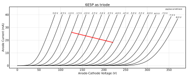
Or 6E5P (low Rp, MU about 35...), very linear. Great driver for 4-5€/pcs.Please dont parallel driver tubes, there is much better options. Ec8010, E180F, E280F, D3a.
Another chrap but good solution is EF184 in triode. gain of 55Or 6E5P (low Rp, MU about 35...), very linear. Great driver for 4-5€/pcs.
Ia at 10 mA, around
The curves
Miller capacitance of paralleled tubes can be lowered by higher current available, at least in theory....
Would like hear what more experienced members have to say about these claims.
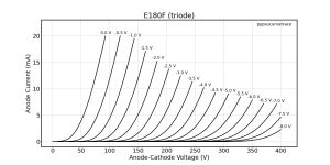
Looking at E280F & E180F datasheets, in triode connection - they can be biased up to Vg-k -4, where the loadlines stop ( Philips & Mullard ds ).
6J9P-E / 6Z9P-E is dirty cheap alternative for E180F and works very good.
Would like hear what more experienced members have to say about these claims.
Looking at E280F & E180F datasheets, in triode connection - they can be biased up to Vg-k -4, where the loadlines stop ( Philips & Mullard ds ).
6J9P-E / 6Z9P-E is dirty cheap alternative for E180F and works very good.
Looking at E280F & E180F datasheets, in triode connection - they can be biased up to Vg-k -4, where the loadlines stop ( Philips & Mullard ds ).
Typical -negative- bias for D3a/E280F/E810F or little brother E180F at about 1.5-2V, so grid swing usually doesn't exceed 4V.
These tubes suitable to drive 300B (150-180Vpp grid swing), so 2A3 requirement (90Vpp) is easy job (with under 1V input).
I see what you mean. The secondary center tap is connected to GND, and so is the DC-. I guess the PSU circuit needs some work anyway, but as long as the audio circuit is not set it's hard to tell what it needs from the PSU.Did anyone else notice that the drawing shows a 600vCT power supply? With the negative 300v shorted to ground? :^)
You'll want to stay away from grid current, which typically starts at about -0.5 V at the grid. A "pro audio" signal will nominally swing +/- 1.8 V, so the DC bias at the grid should be at least -2.3 V. However, todays audio sources tend to have a much larger voltage swing, so I'd consider -3 V as a minimum.Typical -negative- bias for D3a/E280F/E810F or little brother E180F at about 1.5-2V, so grid swing usually doesn't exceed 4V.
It would make sense to think about the needs for the input/driver stage first, and then select a suitable tube type. With a +/-1.8 V = 3.6 Vpp input and 90 Vpp at the 2A3 grids, you need a gain of 90/3.6 = 25.
The 25x gain happens to be pretty much the same as what I needed for the OSDEHA amp, and I looked at various data by Pete Millett, Klausmobile, and Ale Moglia (see here). I ended up testing samples of the E180F, D3A, ECC88 and 6E5P. I preferred the 6E5P (see here and here).
Would it make sense to insert a FET source follower between the input stage and the 2A3 grids to properly drive the DHT grids (aka "Power Drive" as coined by Tubelab)?
Last edited:
You'll want to stay away from grid current, which typically starts at about -0.5 V at the grid. A "pro audio" signal will nominally swing +/- 1.8 V, so the DC bias at the grid should be at least -2.3 V. However, todays audio sources tend to have a much larger voltage swing, so I'd consider -3 V as a minimum.
Typical -negative- bias for D3a/E280F/E810F or little brother E180F at about 1.5-2V, so grid swing usually doesn't exceed 4V.
Neither of these high gm trioded pentode working -as VAS- at -3V bias (near to the close down, without enough headroom).
I usually use these tubes at 1.5-2V bias with satisfaction.
I'd tend to disagree. See attached curves of E180F, 6E5P and D3A configured as triodes.Neither of these high gm trioded pentode working -as VAS- at -3V bias (near to the close down, without enough headroom).
Attachments

- Home
- Amplifiers
- Tubes / Valves
- Yes another 2A3 design I am ready to be judged