last weekend I have heard two different power amplifiers by direct comparsion:
1) Pass "X 600" vs.
2) Yamaha "MX 10.000" (MX10000, MX-10000)
I was surpriced about the low sonic differences between this two devices and I guess, that the HCA technology is also a good solution, especially if the loss power must be lower by the same output power.
Are there HCA diy projects respective other commercial amplifier brands, where is HCA technology inside?
Last edited:
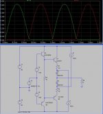
Pair of Schottky non-linear resistances spanned between two offset followers
gives the following push and pull currents into the load: I've never been sure
if this behavior was Class A? or Class AB? Maybe its your Hyperbolic thing?
Is there a schematic of the OPS?
Damnit, MX-1000 and MX-2000 (amps with the same feature) service manuals are missing the pages that have schematics!
Anyone have these?
Anyone have these?
cbdb>Is there a schematic of the OPS?
Yes.
This circuit I am about to show you is an older one, created the above plot.
Certainly not the simplest, nor best way I could have drawn for you today.
Magic is simply two independent single ended class A amplifiers, any type will do.
Offset one amplifier to track one emitter drop above the desired output voltage.
Offset the other one to track one emitter drop below the desired output voltage.
A quiescent current is set by resistors spanning the gap between these two offsets.
If that resistance is linearly resistive, then only linear class A crossing can be the
result... Power wasted at quiescent is exactly the same as at full output swing.
But if that resistance rides on the curve of a non-linear diode.... You can shape it.
The Quiescent current can be far less than full output swing. But still no transistor
is ever turning off.
This is my own circuit, nothing to do with Yamaha's. And possibly irrelevant.
We still at this point know nothing about "Hyperbolic" to guess what that means?
But the Yamaha advertised description (so far) fits how mine behaves to a tee.
Is Yamaha using the same trick, or I've spun completely off a different tangent???
Attachments
Last edited:
Hi
I think that you can find both service manuals and schematics at Jan Dupont’s website ACD
http://www.audio-circuit.dk/
BTW look at patent US4803441
Cheers
I think that you can find both service manuals and schematics at Jan Dupont’s website ACD
http://www.audio-circuit.dk/
BTW look at patent US4803441
Cheers
Darn, and I thought MY way (with a big Schottky) overcomplicated.
Yamaha looks like an analog computer based upon log nonlinearity of
bipolar transistors??? How they keep that from becoming temperature
dependent? A Schottky on the other hand dissipates almost nothing
in this application compared to the capability of its TO220 package...
But I think we are talking the same end result, as far as current go.

this all sounds like barry thornton's "hypersonic class a" from those old (and nice i thought SAE amps). i think he used schottkys in the output stage also.
hmmm ... maybe i shoulda kept quiet, i might be dating myself again ...
mlloyd1
hmmm ... maybe i shoulda kept quiet, i might be dating myself again ...
mlloyd1
Its far easier to match curve of an identical two terminal diode to compliment
the same on the flip side...
Than trying to match up swervie-curvies of an NPN to PNP, especially if those
same devices are also the ones dissipating the big power... Many of the purpose
built complimentary pairs have lots of emitters with series resistance, too linear.
Just build in some error correction, and let them be as linear as they wanna be,
why fight it?
The Schottky can't drop more than .3 forward volts, so its largely out of the
power dissipation business at any realistic Class A current. But it gives back
the curves we need to achieve this A-AB-hyperbolic crossing or whatever it is...
I think that you can find both service manuals and schematics at Jan Dupont’s website ACD
Unfortunately not, since (like I wrote earlier) there are no schematics in those service manuals - at least not in the .pdf files circulating in the Internet. 🙁
The patent luckily sheds some light on this thing, though.
hmm, see this Yamaha MX-2000
http://images.elektroda.net/80_1239723765.jpg
http://images.elektroda.net/14_1239637157.jpg
http://images.elektroda.net/80_1239723765.jpg
http://images.elektroda.net/14_1239637157.jpg
Last edited:
this all sounds like barry thornton's "hypersonic class a" from those old (and nice i thought SAE amps). i think he used schottkys in the output stage also.
A little different - the diodes connected and disconnected the
output transistors from the load. Most of the other schemes
left the emitters (or their equivalents) conducting to the
output.
😎
Here is a non-switching output stage that I invented. Nice and simple. Just add a pair of Schottkey diodes and a pair of constant current sources to a standard double EF (haven't looked at the schemes being discussed, but it's most likely just another "re-invention").
Well, I can guarantee 100% that the output devices never turn off............ 😉
Well, I can guarantee 100% that the output devices never turn off............ 😉
Attachments
Last edited:
Service Manuals about all Yamaha models you can get about here:Damnit, MX-1000 and MX-2000 (amps with the same feature) service manuals are missing the pages that have schematics!
Anyone have these?
http://www.schaltungsdienst.de/48.html (only German)
or call ++49 - (0)30 - 723813
info@schaltungsdienst.de
cbdb>Is there a schematic of the OPS?
Yes.
This circuit I am about to show you is an older one, created the above plot.
Certainly not the simplest, nor best way I could have drawn for you today.
Magic is simply two independent single ended class A amplifiers, any type will do.
Offset one amplifier to track one emitter drop above the desired output voltage.
Offset the other one to track one emitter drop below the desired output voltage.
A quiescent current is set by resistors spanning the gap between these two offsets.
If that resistance is linearly resistive, then only linear class A crossing can be the
result... Power wasted at quiescent is exactly the same as at full output swing.
But if that resistance rides on the curve of a non-linear diode.... You can shape it.
The Quiescent current can be far less than full output swing. But still no transistor
is ever turning off.
This is my own circuit, nothing to do with Yamaha's. And possibly irrelevant.
We still at this point know nothing about "Hyperbolic" to guess what that means?
But the Yamaha advertised description (so far) fits how mine behaves to a tee.
Is Yamaha using the same trick, or I've spun completely off a different tangent???
The MX-10000 circuit looks like a bridge amplifier without overall NFB and consists basicly two operational amplifiers and two power buffers - one pure class A (low voltage supply) and one class AB (high voltage supply). The first stage is a complete independend voltage gain amplifier (55 times).
The output stage of this one drives
1) the class AB power buffer (the output of class AB power buffer goes to the positive speaker terminal) and
2) the inverted input of a summing amp about a 6K8 resistor (non inverted input of this summing amp goes to GND)
The output of this summing amp (ERCO amp = Error Correction amp) drives the second power buffer, that is the pure class A buffer (the output of this buffer goes to the negative speaker terminal and also to the inverted input of a summing amp about a second 6K8 resistor
So I have a mixed signal between an (more or few) undistorted signal version from the voltage gain stage output and a distorted (and inverted) signal version from the neg. speaker terminal at the inverted input from the summing amp.
I cannot explain, why Yamaha calls this technology so than the head line of this thread.
If I replace the pure class A buffer through a "ZEN" or other simple single ended topology and the class AB buffer through an simple power buffer with 30-50 mA idle current, I get interest possibilities for diy projects (together with appropriate OP amp models for the voltage gain and ERCO amplifier stages).
This goal from Yamaha was the same than that of Quad's current dumping topology and the main different to Quad 405 power amplifier is the serial mode of the correction amp - Quad choises a parallel mode like the EDWIN amp projects from the Geman magazine "elektor" arround 1970 - 1975.
If I have remove the WIN32/ConflickerC worm from my own personal computer I will upload the basic schematic of Yamaha MX-10000 for better understand.
Last edited:
Discussing a circuit without schematic is kinda difficult so here is the full schematic for those interested.
Tiefbassuebertr, the best way to get rid of conflicker c is to use microsoft s malicious software removal tool, available at updates, look for KB890830.
Tiefbassuebertr, the best way to get rid of conflicker c is to use microsoft s malicious software removal tool, available at updates, look for KB890830.
Attachments
tiefbassuebertr
---Are there HCA diy projects respective other commercial amplifier brands, where is HCA technology inside?---
There are two quite simple schematics for DIY experimentation here :
Ian Hegglun,
"Square law rules in audio power"
Electronics Wolrd +Wirelss World, September 1995, p751 to p756.
Press ENTER to look up in Wiktionary or CTRL+ENTER to look up in Wikipedia
Can anyone post this article or schematics?There are two quite simple schematics for DIY experimentation here :
Ian Hegglun,
"Square law rules in audio power"
Electronics Wolrd +Wirelss World, September 1995, p751 to p756.
Press ENTER to look up in Wiktionary or CTRL+ENTER to look up in Wikipedia
PS. YAMAHA MX-10000 is not the same as MX-1000
Last edited:
- Home
- Amplifiers
- Solid State
- Yamaha's Hyperbolic Conversion Amplification (HCA) Circuit