Hi all. Have removed and tested all the transistors in the tuner pack (TRs 2,3,4,6,7). They are all NPNs and all test OK. The two transistors located adjacent to adjustable coil are Hitachi 2SC3391 which are listed as local oscillator, mixer on the data sheets. So my post immediately above is not correct in identifying the LO. The others are Sanyo 2SC2839. Have not tested last 2 varactors or the item marked TR1 which has 4 pins. Are we reaching the end of the road here? Glenn
I suspect we might be 🙁 but it has certainly been a great learning exercise.
The goalposts moved (as I mentioned earlier) with the discovery of AM working manually. See what the others think but I suspect its reached a point of no return and that its not worth expending the effort on... however if you did want to pursue it as a learning exercise then I think getting another similar unit would be the way to go. You could then swap the cans over and take it from there.
The goalposts moved (as I mentioned earlier) with the discovery of AM working manually. See what the others think but I suspect its reached a point of no return and that its not worth expending the effort on... however if you did want to pursue it as a learning exercise then I think getting another similar unit would be the way to go. You could then swap the cans over and take it from there.
You can not get the LO to put out a signal? on bench power, it consists of 1 bjt, varactor, some passives. not too much to go wrong. methods of substitution.
Got it- post 122. Thanks. Will it be an issue that all the earth connections are now disrupted now that the metal shroud has been removed. Glenn
OK thanks. Better explain where to connect the power- Vt pin and earth pin or direct to the transistor? That might be a dumb question but this is new territory for me. Glenn
You are going to have to do some investigation on the pin out of the FM pack to determine what pin does what. Determine the grounds, see what pins are common to each other and where they go to what devices.
You could post a pic of the backside of the FM pack so I can take a look.
The back side of the TX-550 pcb in that manual can be a little help as it shows, not very clear, how it is wired up. The schematic of the TX-550 can be of some help as well.
supply should be 12V the FM pack and the varactor V can go as high as 30V but you can test with it being at 12V.
Hi Glenn,
You can power and run the tuner pack out of the unit. As mentioned, your power common goes to the ground (shield attachment points or terminal) and power, likely 12 VDC, goes to the B+ pin, or power pin seen on your schematic for your tuner. Then you apply a variable voltage from the Vt pin. You should see the frequency on the osc out pin that varies with the changing Vt pin voltage. If you monitor the IF out pin, you will find a very to no signal at all. If you attach an antenna to the antenna pin, you might be able to see a weak (low) signal out of the IF out pin. What you are really interested in is the much stronger LO out signal.
Given that the Vt is shared with the AM tuner, you may or may not be able to track the AM LO output. It isn't uncommon for the AM circuits to reside mostly on the main PCB and just the RF tuning parts in the tuner pack, or the entire AM tuner may live on the main PCB, which I expect would be the case here. I'm not looking at the schematic for your tuner right now so that is why I'm using terms like "may" or "normally"
You are getting close to the end of this. Did you replace those two capacitors yet? If not, do so as they will really affect any tests you do with the tuner pack mounted on the main board again.
-Chris
Not necessarily. Going by the schematic that Rick posted, there is no error. Keep in mind that the intended use of the part listed by the manufacturer is just a guide. If the part is good for a local oscillator, it will also work fine as a mixer or buffer or (depending on noise) an RF amplifier. This is contrast to a low level audio (low frequency, low noise) application.So my post immediately above is not correct in identifying the LO.
You can power and run the tuner pack out of the unit. As mentioned, your power common goes to the ground (shield attachment points or terminal) and power, likely 12 VDC, goes to the B+ pin, or power pin seen on your schematic for your tuner. Then you apply a variable voltage from the Vt pin. You should see the frequency on the osc out pin that varies with the changing Vt pin voltage. If you monitor the IF out pin, you will find a very to no signal at all. If you attach an antenna to the antenna pin, you might be able to see a weak (low) signal out of the IF out pin. What you are really interested in is the much stronger LO out signal.
Given that the Vt is shared with the AM tuner, you may or may not be able to track the AM LO output. It isn't uncommon for the AM circuits to reside mostly on the main PCB and just the RF tuning parts in the tuner pack, or the entire AM tuner may live on the main PCB, which I expect would be the case here. I'm not looking at the schematic for your tuner right now so that is why I'm using terms like "may" or "normally"
You are getting close to the end of this. Did you replace those two capacitors yet? If not, do so as they will really affect any tests you do with the tuner pack mounted on the main board again.
-Chris
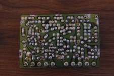
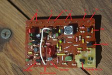
Hi Rick, Chris, have attached image of underside of tuner board. Worse for wear now that I have been working on it. Have also attached another image of top of component side of board showing my take on what is what. The two pins which I have not labelled must be VCC and IF out but not sure which is which. E is earth. Glenn
Attachments
That helps a lot Glenn,
The IF transformer is the metal can with the black tuning slug, one of it leads, the secondary IF o/p will go to a pin. The other side of the secondary will be at ground potential. The primary will have one end that goes to the supply, goes through a R10. The other end of the primary goes to the mixer Tr2.
I only see 3 ground pins, check for resistance to confirm. follow the traces
Suggest to label the pins arbitrary so that we can agree on function. it does not matter left to right or vise versa, as long as they are in a sequence so we can refer to them and match against the schematic.
Rick
Last edited:
Hi Rick. I think the IF transformer has 3 leads going through the board as far as I can see. Plus two tabs for the casing which are to earth. Schematic shows 4 but I can't see another one- is the casing to earth the fourth lead? The 3 leads I can see are connected to ground (and to the casing on the IF transformer). In fact they there is continuity between all 3 leads and all the pins marked E in that second image I posted earlier. That seems odd and is not consistent with what you say above or the schematic. Glenn
Rick, further to last post, found 2 more connections between IF transformer and board. They are in fact in continuity and go to C9 and collector on TR2. So must be one end of primary- that is good. However, I cannot see any connection between the IF transformer and a resistor (R10)- other end of primary. Nor can I see any connection between IF transformer and a pin other that one that is ground ie. cannot see secondary IF o/p to pin. I will try to locate R10 and work back towards IF transformer. Glenn
The IF can usually has 2 wider leads for the can and 2 or 3 on each side for the windings. Windings can be any direction, but usually are confined to a side.
The windings are very low ohms. so for the IF primary you should measure the value of R10 from VCC to the collector of Tr2, usually around 100 or so.
The windings are very low ohms. so for the IF primary you should measure the value of R10 from VCC to the collector of Tr2, usually around 100 or so.
That is right C9 couples the IF sample into Tr6 which is biased to amplify and then get diode detected by D5, this forms the AGC bias for Tr1
Rick, further to last, have located what I think is R10. It is shorted- continuity between leads. One lead of R10 connects to pin second along from OSC pin so that must be VCC. There is continuity between R10 and collector on TR2 which suggests that the IF transformer is shorted also (I see a capacitor inside the the IF transformer on that circuit so maybe that is shorted). Glenn
- Status
- Not open for further replies.
- Home
- Source & Line
- Analogue Source
- Yamaha TX540 tuner not tuning