Hi Glenn,
Normally cheap = a PITA to use.
The trick is very low pressure from the soldering iron no matter what you are doing. That will work for braid, and for the solder sucker. One main advantage about the solder sucker is that it removes most of the heat energy along with the solder. Wick doesn't do that.
-Chris
Thanks Chris. Have replaced those caps, soldered board back in without the shroud and reconnected the Pot for tuning. Lo and behold, can now tune both AM and FM. Amazing. FM is as clear as a bell and in stereo and picking up all local stations. However, tuning display not moving and signal strength meter not registering in FM. AM reception not as good as it was but can still tune stations using small indoor antenna. Tuning display not moving but signal strength meter is working in AM. Still have a transistor out of board and a resistor lifted as per Mooly's instruction to connect pot. Glenn
Hi Glenn,
Okay, pull the tuner pack and put it all together properly, then stick it back in. Once that is done you can try it again and list what is working and what is not. I had assumed you were going to put it all back together except for the shields when you tried it again..
It might not be a bad idea to put those parts back in and try it again without the shield. If the sensitivity is low without the shield, don't worry. Once everything is working, put the shield back on and stick the tuner pack back in for good.
-Chris
Hi Chris, job done. Can manually tune both AM and FM with dial but auto tuning not picking up stations. Signal strength meter working on some low freq am stations (94.9) but not on higher freq stations. Signal strength meter appears to work fine on AM. Glenn
Chris, further to last, signal strength meter now appears to work on other FM stations. Using indoor anetenna and gave it a jigggle. Auto tuning still not working though. Maybe the aerial. Glenn
Moved antenna to better position. Auto tuning now working as is signal strength meter. So, all is now working OK as far as I can tell. I am amazed. Glenn
Moved antenna to better position. Auto tuning now working as is signal strength meter. So, all is now working OK as far as I can tell. I am amazed. Glenn
And so am I 🙂 but very pleased it is making all the right noises.
Are we saying it has 'healed up' with no parts replaced? It does happen that way sometimes unfortunately leaving you wondering...
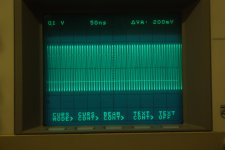
Edit... it would be interesting to see if the scope now shows the local osc signal at the LM7000. With the tuner working correctly, that signal must be present. Can you now see it?
Hi Mooly. I did replace the two caps on the board linked to AMIN. As it turns out they were not that far out of spec. Maybe there was a cracked solder joint in the tuner and it got fixed with me pulling bits out and putting them back in. Anyway, all looks fine at the moment. Just have to put the metal case back on the tuner. Lots of solder points on that metal case. Hope it goes together OK. I take it the metal case is for shielding. I was looking forward to checking some signals out with the scope to see what I was supposed to see. I'll let you know. Glenn
Yes, the metal case is mainly for shielding, not just to stop stuff getting in but also to stop stuff radiating out.
It will be interesting to see if the scope shows a more expected type signal on the osc output now.
It will be interesting to see if the scope shows a more expected type signal on the osc output now.
I guess I don't have to be meticulous about soldering the case back on. There was a lot of solder on the sides.Had to use a larger soldering iron to get it off. Hopefully it will re-join when it gets heated. Glenn
And what should it look like?
A sine wave, the frequency will depend on the actual station tuned and I would expect it to be the station frequency plus 10.7MHz which is the FM IF frequency.
I think Rick looked at the data sheet for the LM7000 some while back and mentioned it quoted between 100mv and 1.5 volts as acceptable levels. Those are RMS levels and so should be around 280 millivolts peak to peak as a minimum. Remember this is over the 100MHz bandwidth of the scope and so the actual amplitude you see could be down a little.
Hi Glenn,
Good show. Now its sorted.
Hi Mooly,
I have seen a few like this, fixed by replacing those cheap capacitors. I'm not surprised at all.
-Chris
Good show. Now its sorted.
Hi Mooly,
I have seen a few like this, fixed by replacing those cheap capacitors. I'm not surprised at all.
-Chris
Hi Chris. Played if for a couple of hours tonight and all good. Still need to install the case and reassemble. It was an adventure. Thanks for your patience and Mooly's as well. Thanks Nick also- learned a bit about IF transformers last night! I'll check with the scope and report back in a couple of days. Glenn
Hi Glenn,
As long as you work without rushing as you put it back together, you should have a very nice tuner that runs for years to come.
-Chris
As long as you work without rushing as you put it back together, you should have a very nice tuner that runs for years to come.
-Chris
 I thought it had passed the point of no return.
Hi Mooly,
I just brought it back to a point where your questions could be answered, that's all.
-Chris
I just brought it back to a point where your questions could be answered, that's all.
-Chris
Hi Chris, Mooly, have attached oscilloscope trace from OSC pin on tuner board. Station tuned is 94.9 FM. Glenn
- Status
- Not open for further replies.
- Home
- Source & Line
- Analogue Source
- Yamaha TX540 tuner not tuning