I think I burned some IC regulators because of my bad test of yesterday, The values received seem to be wrong, for example yesterday on the first IC I geted the correct value which is "+12V" and now I get 1.30 ...
OK, please measure below voltages after the bridge rectifier, one probe on jumper 0, the other probe test jumper 1 and then jumper 2.
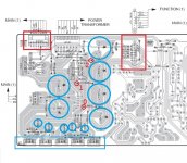
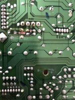
In the video, I saw the bigger caps quality is not so good, I think you should replace all the regulator ICs and all the caps together and hope the power supply board can work after the replacement. I marked the replacement regulator ICs and caps in blue color.
Attachments

Last edited:
OK, please measure below voltages after the bridge rectifier, one probe on jumper 0, the other probe test jumper 1 and then jumper 2.
Thank you again for your help patrick
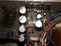
This is the bridge ?
Attachments
Measure using DC Voltage function/mode, not diode mode. Black probe connected to chassis.Ok, I mesure that with diode mode ?
Thank you again
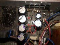
power on and measure the voltages
I'm really sorry but you want me to test theses 3 wires ?
Attachments
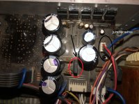
measure below voltages, one probe on jumper 0, the other probe test jumper 1 and then jumper 2.
Attachments
Last edited:
measure below voltages, one probe on jumper 0, the other probe test jumper 1 and then jumper 2.
Ok i will do it and i will come back with the results
Thank you!
I think that the game is over, I found it :
It is not difficult to fix these broken PCB traces, but first you have to find out all the bad components, replace them and reconnect the broken PCB traces, then you can test the board again
It is not difficult to fix these broken PCB traces, but first you have to find out all the bad components, replace them and reconnect the broken PCB traces, then you can test the board again
Thank you Patrick,
To do that I need an electronic specialist and is not easy to find one with this health crisis...I do not see myself doing this alone unfortunately :/
Did you see the video of the test 3 wires ?
Best regards
Thank you Patrick,
To do that I need an electronic specialist and is not easy to find one with this health crisis...I do not see myself doing this alone unfortunately :/
Did you see the video of the test 3 wires ?
Best regards
I watched the video and it can not help to tell what is wrong.
HI,
I have a question please,
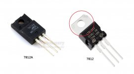
Can I replace the : 7812A and 7805A IC by 7812 and 7805 IC ?
Best regards
I have a question please,
Can I replace the : 7812A and 7805A IC by 7812 and 7805 IC ?
Best regards
Can I replace the : 7812A and 7805A IC by 7812 and 7805 IC ?
The package is different, normal 7812/7805 the heatsink fin is exposed, but it is the ground pin for a positive voltage regulator, so that it should be no problem to use them to replace the A version.
Attachments
Thank you again,
Well I received the : +12v and two +5v tension regulators today and I changed them,
When I tested the amp with only these two cable connected :
20/17/jvm5.jpg - Visionneuse Zupimages
+12, +5 and +5t tension regulators give me correct output +12v, +5v and +5v, the diagnostic message changed now I have now PS PRT 064 D (In the past had this message PS PRT 000 D)
When I tested with all cable conneted include this one :
20/17/d3p8.jpg - Visionneuse Zupimages
I have wrong voltage, for example +5V give me 3.14V (diagnostoc message : PS PRT 009)
I haven't changed the negative voltage regulators because I can't find them
this may be the cause of the problem ? I'm really lost 🙁
I haven't changed the negative voltage regulators because I can't find them this may be the cause of the problem ? I'm really lost 🙁
Do not hurry to test it without all the regulators get replaced.
How about the back side of the PCB, do you repair it good.
Attachments

Last edited:
How about the back side of the PCB, do you repair it good.
Unfortunately no, how can I fix this?
Thank's Patrick
Do not hurry to test it without all the regulators get replaced..
Yes I am looking for how can I get the negative regulator as soon as possible
- Home
- Amplifiers
- Solid State
- Yamaha RX-V 550 turn on 1-2 seconds and then turn back off