Hi Folks;
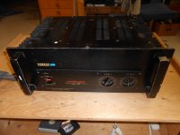
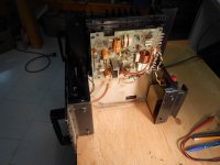
I own a Yamaha P2200, which I feel is a great sounding, well made, and nice looking amp, so when I saw this P2201 (non VU metered), for parts or repair, I could not resist. I was told that Chan A "may work".
After by-passing the missing power switch, and connecting a load to the output wires ( Ch A speaker binding posts were removed), channel A worked!
Channel B has a defective volume control (knob continues to rotate, set screws are not loose). Ch B output PCB has been disconnected from the power supply, AND has no output transistors.
Question; After addressing the volume control issue, and reconnecting that channel to the power supply, can I power up the unit (via variac) without output transistors?
My plan is, if nothing smokes, I would transfer the outputs from the working channel, to chan B. I understand that this is a complementary push pull design, so I will check the correct location of PNP and NPN outputs. I don't want to order new outputs until I can verify what other components are also required for this restoration.
Thanks again, Peter in Canada.
Attachments
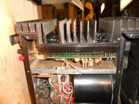
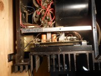
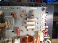
Here's two more 'before' shots;
I appreciate everyone's advice. I think the quality of this amp is rare, these days. The power output is modest by today's standards, but I believe this is a perfect amp for critical HiFi or HF and MF use in active cross-over systems, and worth restoring (?)
I appreciate everyone's advice. I think the quality of this amp is rare, these days. The power output is modest by today's standards, but I believe this is a perfect amp for critical HiFi or HF and MF use in active cross-over systems, and worth restoring (?)
Attachments
This is a PA unit, not HiFi.
Still... I'll always had a soft spot for those monsters. They DO sound very good, especial on diff. loads like Martin logan ect. ( and you can find them dirt cheap from time to time ).
Remember to check bias ect when done. And the E.lytes might have done their job ( at least the small pay'able ones on the back )
T.
Give the driver board a once-over with new small electros and replace any burnt resistors, diodes, transistors (especially drivers and the bias regulator) before powering the board up. If it's like any of the Yammies I've seen it will work at low power (a couple hundred ohm load) with no outputs. Get that working first. Then stick in a single output pair (you have any spare MJ15024/5 pairs on hand?) and verify operation at 8 ohms and that you can properly adjust the bias. Only then buy a new output set as similar as you can to what is in the other channel.
Thanks everyone for all this help, so quickly.
Thanks also wg ski;
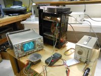
Are you saying that I should see a signal on a 100 ohm load, even with no outputs?
If so, is this an indication that all else is more or less O K?
Thanks also wg ski;
Are you saying that I should see a signal on a 100 ohm load, even with no outputs?
If so, is this an indication that all else is more or less O K?
In any amplifier with emitter follower outputs you can operate off the drivers at reduced power. A good way of testing without risking $50 worth of output transistors (or $200 in the case of that Crest). A dim bulb limiter is still a good idea and will usually prevent fires. You need to find out what if anything took out the original outputs, and if there is some other fault like DC rail voltage to the speaker. Correct all of this first. When everything else is ok, you can play music through it - with a 100 ohm resistor in series with the speaker - and it will sound good.
PS;
I will do a thorough visual inspection before powering up the unit. The outputs are 2SC1586 (npn) and 2SA909 (pnp). I am told that they are discontinued and will search for substitutes.
Do you not like the idea of temporarily borrowing from the other channel?
Also in a downloaded service manual the transistor numbers are both followed by; "0,Y" Is this significant?
Sorry if these questions a rather basic, but I do not have formal training in this field, it has just be a life long interest.
I don't like the idea of temporarily borrowing discontinued ouputs, no. I'd use something else entirely before doing that.
O and Y are hFE grades. It was more significant back when that amp was built than it is today (for output transistors, still is today for matching diff pairs), and when any given transistor could come from any lot and they had to mix without doing any testing or pre-selecting on the production line.
O and Y are hFE grades. It was more significant back when that amp was built than it is today (for output transistors, still is today for matching diff pairs), and when any given transistor could come from any lot and they had to mix without doing any testing or pre-selecting on the production line.
And honestly i would operate the channel without a load at first, to see if the thing is producing DC. Once the amp is stable and not making DC, THEN connect a load.
The drivers might be OK with a light load, but if they try to put DC on one, it may stress them.
The drivers might be OK with a light load, but if they try to put DC on one, it may stress them.
Something has gone horribly wrong in at least a couple of places. I started to feel that this amp is going to be an 'organ donor', but I'm not giving up that easy. However, this project is somewhat intimidating because of my limited experience, and the initial problem has been compounded by some unsuccessful repairs.
I have the schematic, and the other channel to what is damaged or removed.
Do these old amps have a common failure mode?
I have the schematic, and the other channel to what is damaged or removed.
Do these old amps have a common failure mode?
Attachments
Do these old amps have a common failure mode?
Shorted output transistors from sustained or repeated overload, with lots of collateral damage.
Failures in the bias stack, which cause shorted output transistors, with lots of collateral damage.
Oxidized connections, from 20 years of heat for a resistor, which can open up and cause lots of collateral damage or just to put DC to the speaker.
Old electrolytics which can cause aberrations in the frequency response or nuisance failures like relays not clicking in like they are supposed to (the Crests do this).
Chances are you had #1 or #2, and they took the outputs out so the other channel would operate. #3 and #4 could be lurrking, and a careful methodical rebuild of that board which you need anyway should address it. Just be sure to clean off all of the carbon off the board where resistors burnt up. Even if you have to scrape off a layer or two. That stuff is partially conducting.
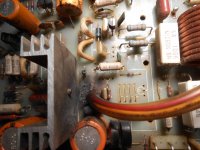
Thanks wg ski, and everyone;
I'm afraid things are looking bleak for this amp at the moment. I removed the damaged module and placed it beside the 'folded out' good channel...In addition to the missing outputs, there seems to be a number of missing components on the PCB. At first glance, emitter resistors and (driver) transistors. The most disappointing is that the heat sinks are missing for the drivers. As you can see in the attached photo, I don't believe I have too much flexibility for replacing this extrusion. It would be a real feat of 'Macgyverism' to make another heat sink from my parts 'graveyard', that fits and has the same radiation surface.
Any thoughts, guys?
Attachments

Thanks wg ski, and everyone;
I'm afraid things are looking bleak for this amp at the moment. I removed the damaged module and placed it beside the 'folded out' good channel...In addition to the missing outputs, there seems to be a number of missing components on the PCB. At first glance, emitter resistors and (driver) transistors. The most disappointing is that the heat sinks are missing for the drivers. As you can see in the attached photo, I don't believe I have too much flexibility for replacing this extrusion. It would be a real feat of 'Macgyverism' to make another heat sink from my parts 'graveyard', that fits and has the same radiation surface.
Any thoughts, guys?
It wouldn't be hard to reproduce those driver heat sinks from billet aluminum. I'm not that far from you. I can mill a couple of them out if you mail me a sample to copy.
Really your biggest hurdle would be damage to the traces of the pc board itself, but with the low cost of Chinese boards, that's not as major a concern as it used to be either.
Hi jwilhelm;
Thanks so much for the offer. I have just found some heat sink stock from a dead plasma TV that I think can made to fit. Yes, are about 2 and a half hours from me, a lot closer than Sudbury, Where I picked them up! ( I also bought a dead Crest 8001, which will be a nightmare for another thread).
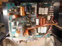
You mentioned "Chinese PCB's". I notice that the working channel has a newer PCB and was installed with little soldering talent. It is not very 'sporting' but can one buy a replacement PCB, preferably with components?
Thanks so much for the offer. I have just found some heat sink stock from a dead plasma TV that I think can made to fit. Yes, are about 2 and a half hours from me, a lot closer than Sudbury, Where I picked them up! ( I also bought a dead Crest 8001, which will be a nightmare for another thread).
You mentioned "Chinese PCB's". I notice that the working channel has a newer PCB and was installed with little soldering talent. It is not very 'sporting' but can one buy a replacement PCB, preferably with components?
I'm not sure if you can buy one already assembled, but it's easy to draw replacements up. Chinese board houses can have replacements at your door in a week.
BTW, I will try to attach the service manual. The image on page 18, component layout for the PCB is mirror image. Is this a view from the 'foil' side? It really looks like a top view but it is reversed from my boards, sorry if this is yet another dumb question.
Thanks again, Peter
Oops, it's too big to attach. It is a 2 meg pdf. It is readily available on line or email me directly and I can happily send it;
hennioriginals@gmail.com
PS; hope this is not improper etiquette
Thanks again, Peter
Oops, it's too big to attach. It is a 2 meg pdf. It is readily available on line or email me directly and I can happily send it;
hennioriginals@gmail.com
PS; hope this is not improper etiquette
- Status
- Not open for further replies.
- Home
- Amplifiers
- Solid State
- Yamaha P2201 Rescued from the scrap heap