Correctly.
And at the Q332 emitter i measure -41.2V
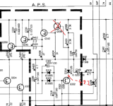
i also tried putting the board on the other side (with jumper wires since its mirrored) to use the other channels V-AMP.
it is using each I-Amp's output in a feedback loop feeding back into the input.
i tought it may oscillate or something making the amp think its in a higher power state.
its known to cause issues like oscillating and blowing up things down the line when it decides to.
as seen in this thread. https://audiokarma.org/forums/index.php?threads/yamaha-mx-1000-and-hi-all.968308/page-2
but i didnt see any oscillations on my scope, nor did it help swapping it from right to left.
measured a few spots again after letting it settle for a minute with Q338 removed just to sum it up:
R388 R392 junction -17.1V
R388 R390 junction 18V
Q332 base -41V
Q332 emitter -41.6V
Q330 base 25.3V
Q330 emitter 25.9V
+HB 95.6V
-HB 95.6V
+LB 41.4V
-LB 41.4V
D324 anode/back -54V
D322 cathode/tip 38.3V
And at the Q332 emitter i measure -41.2V

i also tried putting the board on the other side (with jumper wires since its mirrored) to use the other channels V-AMP.
it is using each I-Amp's output in a feedback loop feeding back into the input.
i tought it may oscillate or something making the amp think its in a higher power state.
its known to cause issues like oscillating and blowing up things down the line when it decides to.
as seen in this thread. https://audiokarma.org/forums/index.php?threads/yamaha-mx-1000-and-hi-all.968308/page-2
but i didnt see any oscillations on my scope, nor did it help swapping it from right to left.
measured a few spots again after letting it settle for a minute with Q338 removed just to sum it up:
R388 R392 junction -17.1V
R388 R390 junction 18V
Q332 base -41V
Q332 emitter -41.6V
Q330 base 25.3V
Q330 emitter 25.9V
+HB 95.6V
-HB 95.6V
+LB 41.4V
-LB 41.4V
D324 anode/back -54V
D322 cathode/tip 38.3V
Last edited:
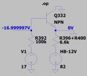
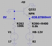
Q332 is specified as a 2SC2705, suffix "O" or "Y". An "O" has an hFE range of 80 - 160. A "Y" has an hFE range of 120 - 240. I'm going to assume an hFE of 120 for a good one. We are down to a pretty simple LTSpice sim for this area, and running the sim with an hFE of 120 gives me:

To get the Q332 emitter anywhere near -41 volts requires me to drop the hFE to 20.

I believe you have said you have changed out or swapped that transistor a number of times with no positive results. Is there anything on the board that may be causing you to install it with the leads in the wrong holes?
The current into the emitter of Q332 should be in the area of -8.5 to -9 mA. I can also force the emitter to -41 V by injecting a leakage current of -21 mA into that node.
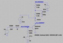
If you are sure that Q332 is a good part, and it is installed correctly, you could try measuring the emitter current available. With Q338 still removed... Set your meter to read current, Red lead on ground, black lead on Q332 emitter. With a direct short to ground, the current is going to be a little higher than if Q332 is properly operating in it's linear region, but you should not see more that 15 mA.
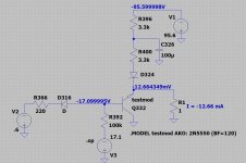

To get the Q332 emitter anywhere near -41 volts requires me to drop the hFE to 20.

I believe you have said you have changed out or swapped that transistor a number of times with no positive results. Is there anything on the board that may be causing you to install it with the leads in the wrong holes?
The current into the emitter of Q332 should be in the area of -8.5 to -9 mA. I can also force the emitter to -41 V by injecting a leakage current of -21 mA into that node.

If you are sure that Q332 is a good part, and it is installed correctly, you could try measuring the emitter current available. With Q338 still removed... Set your meter to read current, Red lead on ground, black lead on Q332 emitter. With a direct short to ground, the current is going to be a little higher than if Q332 is properly operating in it's linear region, but you should not see more that 15 mA.

Thanks for your help, really appreciate it. i never intended for this repair to require this much effort and time.
as i wrote, i moved all transistors on the APS except the power ones from the good to the bad board, without any change.
i was thinking of silk-screen being wrong in some places but everything is where it should be.
The transistors used are all Y marked, both 2SC2705 and 2SA1145
the yamaha manual states O or Y grades with no indication of them needing to match / pair.
All measurements are done with a TC1 Tester, not the most accurate but all results i could reproduce within 5% with a dedicated setup that involved a bunch of tangled wires, two psu and two ampmeters.
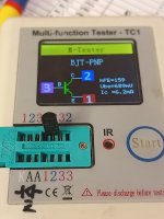
Q338 2SA1145-Y with a hFE=160 at Ic=6.2mA Ube=691mV
Q332 2SC2705-Y, with a hFE=215 Ic=6.2mA Ube=669mV

i attached some pics of the board, i just cant see any issues with wrong component placement. even if the silk-screen would be wrong, i checked that the transistor pins are where they belong.
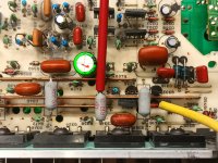

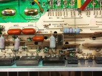
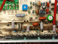
as i wrote, i moved all transistors on the APS except the power ones from the good to the bad board, without any change.
i was thinking of silk-screen being wrong in some places but everything is where it should be.
The transistors used are all Y marked, both 2SC2705 and 2SA1145
the yamaha manual states O or Y grades with no indication of them needing to match / pair.
All measurements are done with a TC1 Tester, not the most accurate but all results i could reproduce within 5% with a dedicated setup that involved a bunch of tangled wires, two psu and two ampmeters.
Q338 2SA1145-Y with a hFE=160 at Ic=6.2mA Ube=691mV
Q332 2SC2705-Y, with a hFE=215 Ic=6.2mA Ube=669mV

i measure 13.1mA (slowly climbing from 12 as it settled.)If you are sure that Q332 is a good part, and it is installed correctly, you could try measuring the emitter current available. With Q338 still removed... Set your meter to read current, Red lead on ground, black lead on Q332 emitter. With a direct short to ground, the current is going to be a little higher than if Q332 is properly operating in it's linear region, but you should not see more that 15 mA.

i attached some pics of the board, i just cant see any issues with wrong component placement. even if the silk-screen would be wrong, i checked that the transistor pins are where they belong.


Crazy. We have a single NPN transistor, configured as common collector. Really basic.
If you short Q332 emitter to collector (GND), what voltage do you see on the base? (should be ~ -17 V)
If you short Q332 base to collector (GND), what voltage do you see on the emitter? (shoud be ~ -0.7 V)
If possible, make these connections/measurement right on the transistor leads - looking for the possibility of a cracked run.


something is going horribly wrong.
Shorting Q332 emitter to collector gave me -41.1V on Base
Shorting Q332 base to collector briefly showed 5.1V on Base (couldnt see if + or -....) then it blew up.
gotta check those diodes and if they turned into Zener or something.... or the foil cap got leaky?!
Shorting Q332 emitter to collector gave me -41.1V on Base
Shorting Q332 base to collector briefly showed 5.1V on Base (couldnt see if + or -....) then it blew up.
gotta check those diodes and if they turned into Zener or something.... or the foil cap got leaky?!
what the heck. saw where the magic smoke escaped.. it wasnt SC2705 even tho it died.
the "undocumented" circuit with 2 diodes facing eachother blew a trace.
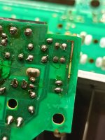
D540(R) D539(L)
and D542(R) D541(L)
took some measurements from the good channel. turns out its a normal diode (yellow ring, no markings) and a 16A zener, measured 15.2V.. probably a 16V one.
clamping base to rail or something.
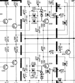
since they blew anyways, im gonna replace them once the new transistors arrive.
maybe the board has been tampered with before.. but i measured the forward voltage of both diodes just fine just not the reverse voltage.
the "undocumented" circuit with 2 diodes facing eachother blew a trace.

D540(R) D539(L)
and D542(R) D541(L)
took some measurements from the good channel. turns out its a normal diode (yellow ring, no markings) and a 16A zener, measured 15.2V.. probably a 16V one.
clamping base to rail or something.

since they blew anyways, im gonna replace them once the new transistors arrive.
maybe the board has been tampered with before.. but i measured the forward voltage of both diodes just fine just not the reverse voltage.
Those diodes are there? Sorry, if I had know they were there I wouldn't have had you short the base to ground. I can't find any documentation for that change - no service bulletins, etc.
16A, not 16 amp.... is it marked 16A? If that 16V Zener was shorted, it could have indeed given you -40 volts on the base. Are you sure it took out Q332? The circuit should work without those 'clamping' diodes installed - I'm sure they are there for a reason, so do put them back in - but you could try it without them.and a 16A zener, measured 15.2V.. probably a 16V one.
i couldnt find any newer service manual that has them included.
yes, its just 16A marked, too small for 16 amps lol its a 16v zener.
it definately took out q332, it now identifies as a diode on emitter collector without base lead.
i suspect someone tampered with this circuit before. they looked a little different than on the other channel.
will test again once the transistors arrive.
The Transistors arrived today, i put them in, replaced those diodes... and it works.
it was that undocumented part of the circuit all the time...
i measured those diodes several times, they seemed fine.
but i didnt measured the zener. someone must have replaced them which and caused all that havoc.
i replaced them with 1n4148 and 16v zener, and the rail is now at -LB.
havent load-tested it yet, but im 99% sure it works.
ive set the bias to 10mV as stated in the manual and closed the lid, gotta replace the terminals once they arrive.
then i give it some load, check the waveforms etc.

finally...
im also happy with the heat distribution, no asymmetry anymore. no unusual cold/hot spots.
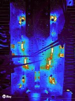
(ignore the hot driver transistors, i forgot to put the bracket on..)
There were a few parts that are not in the schematic.
(some sort of filter at Q333 and Q334 for OCP)
C349, C350 Film Cap 2.2nF 100V
C351, C352 Elec. Cap 1uF 50V
L301, L302 Inductor 12.2mH apparently
R435, 436 Resistor 330k
(Clamping diodes on Q329 Q330 Q331 Q332)
D541, D542, D535, D536 Zener Diode 16V
D539, D540, D537, D538 Diode, yellow ring, probably 1N4148
thanks for your help @Ylli
it was that undocumented part of the circuit all the time...
i measured those diodes several times, they seemed fine.
but i didnt measured the zener. someone must have replaced them which and caused all that havoc.
i replaced them with 1n4148 and 16v zener, and the rail is now at -LB.
havent load-tested it yet, but im 99% sure it works.
ive set the bias to 10mV as stated in the manual and closed the lid, gotta replace the terminals once they arrive.
then i give it some load, check the waveforms etc.

finally...
im also happy with the heat distribution, no asymmetry anymore. no unusual cold/hot spots.

(ignore the hot driver transistors, i forgot to put the bracket on..)
There were a few parts that are not in the schematic.
(some sort of filter at Q333 and Q334 for OCP)
C349, C350 Film Cap 2.2nF 100V
C351, C352 Elec. Cap 1uF 50V
L301, L302 Inductor 12.2mH apparently
R435, 436 Resistor 330k
(Clamping diodes on Q329 Q330 Q331 Q332)
D541, D542, D535, D536 Zener Diode 16V
D539, D540, D537, D538 Diode, yellow ring, probably 1N4148
thanks for your help @Ylli
- Home
- Amplifiers
- Solid State
- Yamaha MX-1000 Class-H stuck rail, cant figure out why