I tested all combinations.
RE,OR,VI DISCONNECT....or CONNECT no difference.
The Amplifier shut off after 2 seconds.
Power supply?
RE,OR,VI DISCONNECT....or CONNECT no difference.
The Amplifier shut off after 2 seconds.
Power supply?
bypassing the c p u is the last things to do,
just to see if the c p u circuitry is normal, but
only after verifying all components are good.
we must make sure there is no short in the amp otherwise will cause further damage.
look for shorts,
DVM diode range....
checking start from the output transistors .
all kind of diodes, start from the rectifiers, zeners ..
all bypassing capacitors ..
resistor range..
compare all channels at the same spot for any difference in resistance.
all resistors ..value changed or opened,
inspect all the boards, observe, look for bad joints
it will take a lot of efforts and time to check all the components,
but many times it only take a while to find the faults.
its the only way and no short cut to find out the faults.
hope you fix it soon.
> checking start from the output transistors .
> all kind of diodes, start from the rectifiers, zeners ..
I'm lazy.
Power amplifiers don't seem to be monitored by the CPU. So why now an effort to check the output transistors? Rectifiers and regulators shall be Ok, we have our DC voltages (including 5.95V, +/-15V to be confirmed, etc). Most of caps shall there be Ok, or we wouldn't have acceptable DC voltages....
> inspect all the boards, observe, look for bad joints
Bad joints, joints oxydation with age, or any suspect electrolytic capacitor. Maybe unplug/replug all the connectors, to clean and reseat them all.
General cleanup (dust removal then isopropyl alcool) could also be welcome, with age, boards and components can be dirty/dusty.
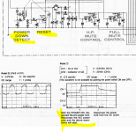
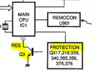
The service manual contains a warning about power/CPU startup. It explains a specific signal is sent to the CPU on mains cord pluging, this signal not been fed on actions on the power switch. This might be the first part to be checked in details, before output transistors...
That part could perhaps be tested basically. a/ first check if reset pin (voltage on C13) is high after power up, then b/ lower/release reset pin (via cap C13, Q3 being mounted there in open collector), see if CPU then display starts.
Additionaly, IC2 (close to CPU, for VCC 5V there) would need a quick check also.
If anything basic there, or maybe with the power switch circuit is wrong, it won't start either, I beleive.
> all kind of diodes, start from the rectifiers, zeners ..
I'm lazy.
Power amplifiers don't seem to be monitored by the CPU. So why now an effort to check the output transistors? Rectifiers and regulators shall be Ok, we have our DC voltages (including 5.95V, +/-15V to be confirmed, etc). Most of caps shall there be Ok, or we wouldn't have acceptable DC voltages....
> inspect all the boards, observe, look for bad joints
Bad joints, joints oxydation with age, or any suspect electrolytic capacitor. Maybe unplug/replug all the connectors, to clean and reseat them all.
General cleanup (dust removal then isopropyl alcool) could also be welcome, with age, boards and components can be dirty/dusty.
The service manual contains a warning about power/CPU startup. It explains a specific signal is sent to the CPU on mains cord pluging, this signal not been fed on actions on the power switch. This might be the first part to be checked in details, before output transistors...
That part could perhaps be tested basically. a/ first check if reset pin (voltage on C13) is high after power up, then b/ lower/release reset pin (via cap C13, Q3 being mounted there in open collector), see if CPU then display starts.
Additionaly, IC2 (close to CPU, for VCC 5V there) would need a quick check also.
If anything basic there, or maybe with the power switch circuit is wrong, it won't start either, I beleive.
Attachments

Last edited:
Cannot edit anymore... see also my previous input, about CPU/reset startup circuitry, and the warnig in the manual.
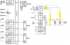
Now I noticed we have two transfomers. Is TR01 powering the CPU? So it is alive permanently?
I would check now first that reset circuitry. Then circuits from the front panel power switch to the CPU.
Startup on mains plugin, then go to sleep two seconds later, until power button pressed, that could be a normal behaviour.
Attachments
That is from the user manual. First entry in troubleshooting section 😀
Did anyone think about opening user and service manuals? 🙂
Did anyone think about opening user and service manuals? 🙂
Attachments

Last edited:
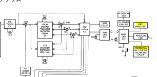
Priority seems so to be:
- CPU power check
- impedance switch and position check
- reset circuit check
- other protection circuits checks, TBD from the service manual and the schematics
If any protection circuit signals a fault, CPU will sure tear the box down also.
Block diagram there being complex. If the CPU locates a fault in any logical circuit (like not responding), other diag steps will be more difficult.
Attachments
Last input for this serie and notes...
Do not know what all other protection circuits could be. Schematics will help.
The CPU has analog I/O ports. One port maybe used to monitor the box temperature. If that circuit is faulty, signals a bad excessive temp, CPU can go to fault states also.
Do not know what all other protection circuits could be. Schematics will help.
The CPU has analog I/O ports. One port maybe used to monitor the box temperature. If that circuit is faulty, signals a bad excessive temp, CPU can go to fault states also.
Attachments
as in #43 stated
before switch on ( bypassing the cpu control)
we must make sure there is no short in the amp otherwise will cause further damage.
I'd stated the necessary procedure,
its only a suggestion, people can take it or leave it.
I'd studied the Yamaha schematics cause it is needed to refurbish my vintage AX-1.
I'm here to offer something clear, easy to understand and helpful ways in fixing the amp,
of cause people can do it their ways.
I respect Mr. Lynyrd , and diyAudio rules.
telling you is easy,
but if others who have insufficient experience, knowledge and skills, doing so could be very bad.
upon your request, I will give you a glue,
if you are up to level, you know what to do.
RE and VI must be unplugged first!
Page 59
SUB POWER SUPPLY
what drives Q101, Q102 to activate the relay to switch on the amp, the c p u!
now how to activate the relay, on and on...
****
since you ignore my suggestions,
you are responsible for yourself.
" I shorted relay on power supply.
The Amplifier shut off after 2 sec "
If someone do a little modification, use a resistor and a switch and wires.
the amp can be switched on and off manually.
if The Amplifier shut off after 2 sec ,
that means the relay is still under control by the c p u.
or Q101, Q102, and the surrounding components are problematic....
if you can not figure out know what to do next,
that is too dangerous to give any suggestion any more.
beware, the relay has fatal AC mains on it.!
Instead of forcing the amp on (which could cause other damages), see what I have added from #44.
Find out what the protection circuitry are: they could indicate in which area the fault is.
And I think I would test around C13 and how that works (reset). A push button there could ease the job, to restart the amp at each push for two next seconds.
Find out what the protection circuitry are: they could indicate in which area the fault is.
And I think I would test around C13 and how that works (reset). A push button there could ease the job, to restart the amp at each push for two next seconds.
You have more than one fault as the fault conditions wont display but you have only 2 seconds , your amplifier,s design relies on being able to see a faults menu which you say doesn't work but the display does work.
So the processor is unable to process information as its not being given it to forward to the display .
So the processor is unable to process information as its not being given it to forward to the display .
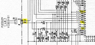
IC5----Pin-71+81+91 should have 5 volts on them ,its a DSP chip and would relate to processing signals ,if its dead that would effect the whole amplifier.
I don't think the box has a diag menu - so far, I didn't read anything about this.
Display and menus being used for box configuration.
Looks like the CPU gets informations from senses, and if any fault condition is raised, the box goes down. See the pictures I added to previous page.
Either the fault is basic (solder joint, or burnt component) or schematics are to be studied, at least, the diag circuits. If a fault is flagged for the CPU (like by a raised signal), that same information (a specific raised signal) could be used to identify the faulty section.
Attachments
- Home
- Amplifiers
- Solid State
- Yamaha DSP A 1 cutting off