What is the most probable problem. I would say some of the output transistors are faulty and that causes the protection to switch the amp off. 😉 Start checking them first.
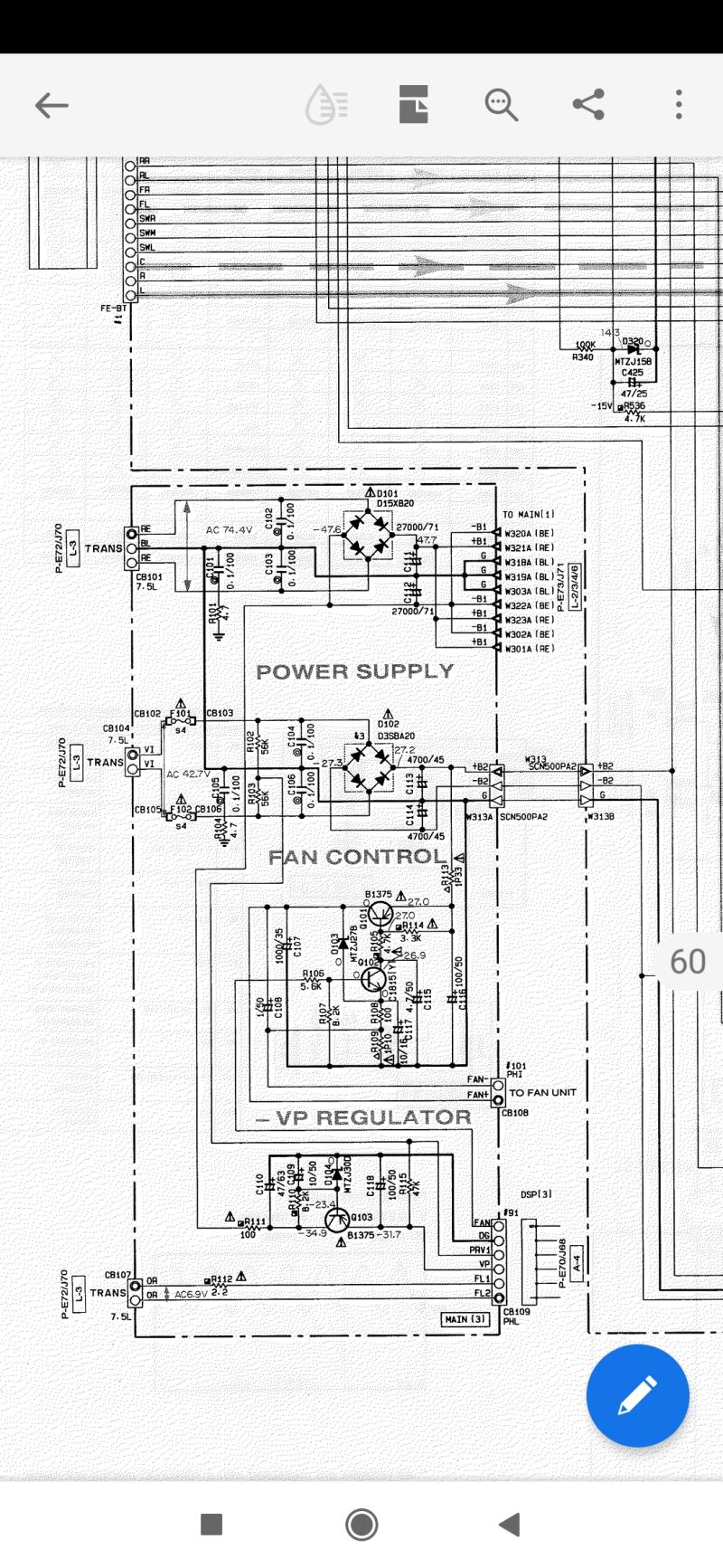
The power transformer have 3 AC voltages.
73.4v RE RE
42.7v VI VI
6.9v OR OR
I have
82v RE RE
46.6V VI VI
6.4v OR OR
What you have is high with 82v and 46.6V. But that seems so Ok: the box is in protection mode, with no load by most of parts, including power parts. So such voltages can get a bit higher.
Then I beleive a litte bit low for the 6.4 you found. Shall be 6.9. Either your voltmeter is inacurate. Or the 5v sections are using too much curent.
6.9 x 1,41 - 1,4 = 8,35, what is needed to generate 5V.
Check some 5V lines, on different boards.
Take care. 73.4v or 82v is letal. Don't touch such sections.
Last edited:
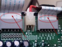
I asked for pictures, saw none. Is this the way boards are mounted?
Can you fully disconnect boards, keeping main, controller and display?
If yes, I would test now 5V rails, then disconnect some boards. To see if 5V / 6.4V rail voltage raise.
If you disconnect power connectors, disconnect also the other signal connectors for the same boards.
Can you fully disconnect boards, keeping main, controller and display?
If yes, I would test now 5V rails, then disconnect some boards. To see if 5V / 6.4V rail voltage raise.
If you disconnect power connectors, disconnect also the other signal connectors for the same boards.
Attachments
If you disconnect the controller and the display, you won't see any error message... Try disconnecting other boards (but fully, don't keep signals connected if you disconnect power connectors)
Amplifier shut down after 2 seconds,no error message
during these 2 seconds I can change the source
during these 2 seconds I can change the source
Last edited:
Assuming your voltmeter is accurate, 15 is lower than 15.7.
Is any IC (on DSP, so on) a little bit hotter than others?
It may get a bit more complex now, assuming the 5V rails are almost correct (4,95V). I saw test points, but they all need an oscillocope.
Processor can bring the box to a safe non workink mode, or that mode (dead) indicating the unit needs maintenance, has also feature to mute everything.
I'm not sure that logical part can be debuged in a easy way.
Attachments
the transformer outputs should be in proportion to the windings as design
but its not here,
two outputs 1/10 higher RE Re, Vi VI, for power amps,
one output 6.9v ok 6.9v is for filaments,
if a Variac is used to lower down the mains to test will be much easier.
or use a dim bulb in series with the mains to test.
****
unplug all the secondary connections of the main transformer,
if it switch on, measure all the AC voltages if they match the schematic.
then
plug back the connections one by one
1) OR, YE if no problem then
2) GY, "
3) VI, "
4) RE,
when plug back the connection and it turn off in 2 seconds,
the problem is there, find it.
****
shooting the problem
unplug the mains plug,
use diode range to test the output transistors and any suspects in the circuit.
I buy a home theatre receiver and after 5- 10 years when it breaks I buy a new one .
It’s too much trouble to take it apart and work on it. Yes you’ll learn something , but theres too much to break inside taking it apart, and a lot of static sensitive large scale ICs
It’s too much trouble to take it apart and work on it. Yes you’ll learn something , but theres too much to break inside taking it apart, and a lot of static sensitive large scale ICs
Last edited:
to encourage your hobby
to narrow down...
just disconnect RE and VI ( unplug )
if no problem
plug back VI,
if problem persist, unplug VI and plug back RE
hope you fix it soon
to narrow down...
just disconnect RE and VI ( unplug )
if no problem
plug back VI,
if problem persist, unplug VI and plug back RE
hope you fix it soon
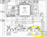
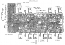
Block diagram is on two pages, huge, with a lot of chips. That won't be fixed by testing transformator and output transistors.
If it is old and cannot be fixed, I would think about pulling out the amp board and heatsinks, the tranfo, the amp PSU, for four channels, maybe to be bridged. With all electrolytic capacitors replacement.
Excedent components (not part of the four channels) to be removed.
.
If it is old and cannot be fixed, I would think about pulling out the amp board and heatsinks, the tranfo, the amp PSU, for four channels, maybe to be bridged. With all electrolytic capacitors replacement.
Excedent components (not part of the four channels) to be removed.
.
Attachments
Last edited:
it looks complicated
but we can narrow it down
to narrow down...
just disconnect RE and VI ( unplug )
if no problem
plug back VI,
if problem persist, unplug VI and plug back RE
but we can narrow it down
to narrow down...
just disconnect RE and VI ( unplug )
if no problem
plug back VI,
if problem persist, unplug VI and plug back RE
> if problem persist, unplug VI and plug back RE
All is linked inside, and a processor checks the status. How do you want that box to start with part of secondary power lines unconnected?
I suggested to disconnect some boards, to see if the display would start and show any error (would depend of software capabilities).
All is linked inside, and a processor checks the status. How do you want that box to start with part of secondary power lines unconnected?
I suggested to disconnect some boards, to see if the display would start and show any error (would depend of software capabilities).
of cause there are different ways to diagnostic the problem.
some may be a little hard for Mr. lynyrd
that's why I only introduced the basic methods.
I'm here to offer help
****
For me I would bypass the c p u to switch on after all the secondary windings unplugged to narrow down the fault.
some may be a little hard for Mr. lynyrd
that's why I only introduced the basic methods.
I'm here to offer help
****
For me I would bypass the c p u to switch on after all the secondary windings unplugged to narrow down the fault.
- Home
- Amplifiers
- Solid State
- Yamaha DSP A 1 cutting off