
I 2nd the suggestion to use spring loaded lead clips instead of pointy probes with lots of exposed metal. Some add insulation/ heat-shrink to the probe metal shaft for all but the tip. Might have saved you in this case. I make my own up, they break and the wire has to be reattached so might as well make your own. Panoma leads are premium cost vs making your own. Also suggest to connect/disconnect them while power is off.
As for the repair, many focus on measuring voltages which is fine but you have to identify what components are failed and for that your DMM in ohms and diode test mode is what I use mostly. It’s pretty easy to determine if a bjt is faulty doing the 6-way lead test. In many cases resistors need isolation from the circuit to measure properly, in that case, lift one lead. Other times it’s obvious to test in circuit to see if they are open or way out of spec.
Turn this unfortunate circumstance into a lesson in good troubleshooting practices.
If the output bjts are open/short, probably the Toshiba 2sa1943n/2sc5200n are suitable if originals are in a to-3p plastic package. Drivers, probably Toshiba tta004b/ttc004b
I have a rx-900/u that had a blown channel that I repaired awhile ago.
Good luck
Last edited:
Found Q329 to be bad/shorted. R355 was also burnt but still ohmed out but I replaced it anyway. Tested and now relay engages. Set R channel to exactly 6mv. L channel will not set. I can get it to .7mv. Offset voltages are now about 112 mv on each channel.
So this is where I am at
So this is where I am at
look at your bias spread voltage across Q319,321 emitters, is it, does it behave the same on both channels?
If it behaves the same and the bias wont go uo then down stream there are still isuues. imo I'd replace everything on the OPS, bjts, 0.22, 0.47, use the toshiba 2sc5200n/2sa1943n,
If it behaves the same and the bias wont go uo then down stream there are still isuues. imo I'd replace everything on the OPS, bjts, 0.22, 0.47, use the toshiba 2sc5200n/2sa1943n,
emitter voltage on Q319 is 345mv
emitter voltage on Q321 is 27 vdc
emitter voltage on Q320 is 464mv
emitter voltage on Q322 is neg .675 vdc
emitter voltage on Q321 is 27 vdc
emitter voltage on Q320 is 464mv
emitter voltage on Q322 is neg .675 vdc
now that I look at it again, measure across Q315, Q317 emitters.
OPS bias spread is measured at the top of the Emitter follower chain, with one probe on each emitter, they show it should be around +/-1.2V or 2.4VDC absolute. Use lead grabbers, attach/detatch with power off.
OPS bias spread is measured at the top of the Emitter follower chain, with one probe on each emitter, they show it should be around +/-1.2V or 2.4VDC absolute. Use lead grabbers, attach/detatch with power off.
Last edited:
Found Q329 to be bad/shorted. R355 was also burnt but still ohmed out but I replaced it anyway. Tested and now relay engages. Set R channel to exactly 6mv. L channel will not set. I can get it to .7mv. Offset voltages are now about 112 mv on each channel.
So this is where I am at
I'll have a look later 🙂 I'm still reading....
So just to be clear:
The DC offset on both channels is around 112 mv on both?
The idle current (bias) sets OK on one channel at 6mv but on the other?
Next step is to measure the range of voltage the bias generator can achieve. Put your meter across the transistor (red lead on collector and black on emitter) and tell us what the min and max voltage is as you set the preset to one end and then the other.
When you have done that turn the preset to the end that gives the lowest voltage.
Mooly, I will do that later as I have to start getting ready for work. Ill be back later tonight
@Mooly The min is 2.48vdc and max is 6.5 vdc
Something is open circuit in the driver or output stage.
Look at the circuit. You need to understand how this works.
If you have 6.5 volts across the bias generator then the next step is to leave it set at that voltage (and I think I would put the DBT in use now) and measure voltages bfrom the output transistors to the bias generator. The will show where the problem is.
Put the black meter lead on the main amplifier output which is the junction of the four 0.22 ohm resistors (the main speaker plus output) and using that point as a reference measure all these voltage. Those given in the manual are correct.
You should see an incremental rise of 0.6 volts for each base/emitter junction. Look how the six 0.6 volts add up to 3.6 volts and how that is the voltage across the bias generator (+1.8 and -1.8 is 3.6 volts across the transistor).
So with 6.5 volts across the transistor you will find one of those voltages will be much higher and that will show where the problem is. It could be a component or a break in the print.
A real simple comparison between channels is to use DMM diode test mode, red+ on q315-base and blk- on q317-base. You have 6 Vbe’s and a few low ohm resistors in series.
A method I use when troubleshooting (or even verifying a new design before applying power) is to inject current across the vbe multiplier and TEST ITS OPERATION in place. A 9 volt battery in series with a 4.7k resistor is all that’s needed. Inject from collector of VAS to collector of its current source. Switch-off resistors and emitter resistors need to be temporarily pulled. You pull those to test them anyway. When the emitter resistors are put back in, it will top out at 6 vbe. Then put the Rbe’s back in and it should be good to go if the power transistors are ok. And you’ll obviously be able to know which way the pot needs to be turned on first power up.
Very good, but for a lyman, that's a bit too complicated, strict guidance is required, remove this, short that, measure across that, change that in point form. The theroy of op is needed to understand.
It still bothers me that folks do not do a full nodal comparisions with the power off, use the DMM in ohms/diode mode, comparing nodes on each channel, when you have a working channel, once you determine that a voltage is off or it smoked/quit operating etc.
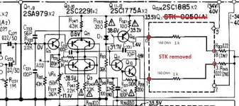
The OPS bias voltages is developed across Q315,317 bases (+/- 1.8V,3.6V), it can be shorted out to test the OPS.
below is a pic I send to help folks determine if the Amp front end is okay before installing a new STK. The current in the voltage amp is in 10mA range
It still bothers me that folks do not do a full nodal comparisions with the power off, use the DMM in ohms/diode mode, comparing nodes on each channel, when you have a working channel, once you determine that a voltage is off or it smoked/quit operating etc.
The OPS bias voltages is developed across Q315,317 bases (+/- 1.8V,3.6V), it can be shorted out to test the OPS.
below is a pic I send to help folks determine if the Amp front end is okay before installing a new STK. The current in the voltage amp is in 10mA range
Attachments
Last edited:
Thanks Mooly, I will start working on that. I found another burnt resistor R383, It connects to the collector of Q331. I replaced it and it just burnt again.
I always leave the amp plugged into the DBT until I am satisfied it is working correctly and obviously this amp is not.
I will do the measurements hopefully tomorrow sometime.
I always leave the amp plugged into the DBT until I am satisfied it is working correctly and obviously this amp is not.
I will do the measurements hopefully tomorrow sometime.
- Home
- Amplifiers
- Solid State
- Yamaha AX-900U