Hi all,
Had come across a very fair deal for a Yamaha A-1 integrated amplifier recently, picked it up, and it is in absolute mint condition with barely any internal dust. Sounds great, however ~feels~ like it is missing a bit of low end punch. With that, it is actually the first amp that seems to bring out great detail in murky basslines. Thus the quandary… does it really need to be touched?
I’ll be checking all the test points shortly to make sure things are in spec voltage-wise, but have been scope-less for a while and won’t be able to do any extensive probing. The capacitors show no visible sign of any bulging, but since it is now a 30-year old amp, I’m sure the majority of responses will be to replace all the electrolytics.
If I do get the itch to start upgrading the odd bits, here’s what I’ve figured so far…
Superficial:
- Replace original flimsy 18AWG power cord with something more substantial (or install an IEC socket)
- Replace speaker posts with gold-plated multi-way binding posts (easy to make a mounting plate)
- Replace lamps with white LEDs (looks like a 12v AC lamp supply)
- Replace headphone jack with something of higher quality (seems to be a bit of static/DC when connecting; will recheck after making sure test values are in range)
Electronic:
- Recap main smoothing caps (original are 10,000/63v) If they can actually fit, would Pocoyo’s 12,000uf Elna be an OK replacement without putting any additional strain on the rectifiers, or transformer secondaries?
- Recap the rest of the PSU regulation board with Panasonic FC (Original are Nippon Chemicon)
- Replace the VD1212 diodes with 1N4148 (as discovered from an Audiokarma thread)
- I have a question about TP1 (-35.09 looks like the test voltage reading? Am I wrong? Schematic will be necessary.)
- Anything else…?
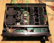
I did get the original manual, which has a beautiful micro-printed schematic. For those who would like a copy, leave me your email address. I’m not sure at what quality I can get it to you, as the 600dpi scan is ~80MB. I’ll keep working on the best way to trim it down, as all the captioning is microscopic. Pictures of the guts will also be posted as soon as I can manage.
I’m still an absolute amateur with more of an electro-mechanical skillset, but can reasonably follow how things work. My M-80 revamp was enjoyable, so hope to keep the momentum of success. Don’t want to risk anything drastic, but would enjoy bringing it back to peak performance if necessary. Any and all insight is always appreciated.
Cheers.

Had come across a very fair deal for a Yamaha A-1 integrated amplifier recently, picked it up, and it is in absolute mint condition with barely any internal dust. Sounds great, however ~feels~ like it is missing a bit of low end punch. With that, it is actually the first amp that seems to bring out great detail in murky basslines. Thus the quandary… does it really need to be touched?
I’ll be checking all the test points shortly to make sure things are in spec voltage-wise, but have been scope-less for a while and won’t be able to do any extensive probing. The capacitors show no visible sign of any bulging, but since it is now a 30-year old amp, I’m sure the majority of responses will be to replace all the electrolytics.
If I do get the itch to start upgrading the odd bits, here’s what I’ve figured so far…
Superficial:
- Replace original flimsy 18AWG power cord with something more substantial (or install an IEC socket)
- Replace speaker posts with gold-plated multi-way binding posts (easy to make a mounting plate)
- Replace lamps with white LEDs (looks like a 12v AC lamp supply)
- Replace headphone jack with something of higher quality (seems to be a bit of static/DC when connecting; will recheck after making sure test values are in range)
Electronic:
- Recap main smoothing caps (original are 10,000/63v) If they can actually fit, would Pocoyo’s 12,000uf Elna be an OK replacement without putting any additional strain on the rectifiers, or transformer secondaries?
- Recap the rest of the PSU regulation board with Panasonic FC (Original are Nippon Chemicon)
- Replace the VD1212 diodes with 1N4148 (as discovered from an Audiokarma thread)
- I have a question about TP1 (-35.09 looks like the test voltage reading? Am I wrong? Schematic will be necessary.)
- Anything else…?
I did get the original manual, which has a beautiful micro-printed schematic. For those who would like a copy, leave me your email address. I’m not sure at what quality I can get it to you, as the 600dpi scan is ~80MB. I’ll keep working on the best way to trim it down, as all the captioning is microscopic. Pictures of the guts will also be posted as soon as I can manage.
I’m still an absolute amateur with more of an electro-mechanical skillset, but can reasonably follow how things work. My M-80 revamp was enjoyable, so hope to keep the momentum of success. Don’t want to risk anything drastic, but would enjoy bringing it back to peak performance if necessary. Any and all insight is always appreciated.
Cheers.
Last edited:
Nice
Thats eally nice amplifier.
You have one of the best amplifers yamaha ever made.
Sounds robust, Clean.
You tried it or not yet?
Thats eally nice amplifier.
You have one of the best amplifers yamaha ever made.
Sounds robust, Clean.
You tried it or not yet?
Actually was chilling-out with it at this moment. Only about my second/third good chance to give it a good intensive listen since I got it last week. Will absolutely get my TT patched in (just fixed it)... Was reading on "The Vintage Knob" how decent the phono preamp is supposed to be.
The more I listen, the less I can nitpick. The bottom end is there, and in fantastic control. Just feels like it may be rolling off a touch early. The sound is a bit forward on HD600's, but that seems to be the "Yamaha sound" (I have an AX-500 to compare it with, among other toys).
Just got the idea to loop it through RMAA...
Offset is minimal at the speaker output. 2mV (left) 12mV (right)
The bass sounds quite 'lean' and 'tight', because of the 2.2µF bypass caps added in parallel with the main filter caps.
http://www2.yamaha.co.jp/manual/pdf/av/english/IntA/A-1.pdf
(values can't be read, but you can see the topology)
This was a very good sounding piece, much better than their larger integrateds (or receivers).
http://www2.yamaha.co.jp/manual/pdf/av/english/IntA/A-1.pdf
(values can't be read, but you can see the topology)
This was a very good sounding piece, much better than their larger integrateds (or receivers).
Schematic for all!
Hmmm, although no quantitative data. I had played with bypass caps on other amps with no perceivable difference. If it is so, it definitely works well here.
Got the schematic down to a 9MB file while keeping as much clarity as possible. Absolutely better than the fax/scan Yamaha provides.
Here's the link ---> RapidShare: 1-CLICK Web hosting - Easy Filehosting
Some interesting notes:
1) The 100ohm (VR501/VR502) offset pots (on the NA07040 board) are incredibly sensitive. Not because of their age, but the fact that they swing from +/- several volts. Is there any way to decrease this range and make it more precise? I predict multiturns would not be of help. I've been able to get it set within a ~10mv deviation from zero, but it differs greatly from when adjusted with the cover off.
2) Bias adjustment is VERY stable. One channel was 8mV, the other was 12... Got them both to a rock-solid 10mV.
3) Regulation/rectifier board was spot-on 35V at the test points. Interesting that the board is installed an an easily removable pin header, making for an easy task of replacing most of the electrolytics when necessary.
4) My output board (NA07130) does not match the NA07039 in the schematic. Wondering if it was an upgrade. My board actually has test points, as measuring bias off of the resistors is relatively impossible.
And regarding my original future upgrade list:
- LEDs can easily be installed, as the original lamps are friction-fit into silicone grommets
- Is it really necessary to replace the VD1212 diodes?
I'm going to leave the amp alone for a bit (and get back to life-sustaining priorities), however appreciate any input on issues that should get attention.
Cheers,
Attachments
Last edited:
i recently recapped the power supply on mine (the only electrolytics utilized if you're not using the phono or tone circuits). if you like the sound now, well...
i risked it and bumped up the smoothing caps a lot, partly because even 27000uF Panasonics are still too small physically but at least workable. i'm pretty sure the transformers do run warmer now, but it's been a few months and i've noticed nothing untoward. i'm sure it would be a good idea to beef up the rectifiers, and someday i might have that done.
results? (the rest of the new caps were ELNA Silmic II's, btw) bass is definitely more solid though it's not a night and day difference. the main result of the recap was removing a layer of haze from the sound that wasn't totally obvious before, and this has really let the tonal accuracy of the amp shine through. i've heard some pretty good vintage gear, including some of the better Yamaha TOTL, and overall this piece is right up there if you ask me. it's not in my main system, but honestly it's just as enjoyable to listen to!
Last edited:
Here's the link ---> RapidShare: 1-CLICK Web hosting - Easy Filehosting
downloadlimit reached.. could you please upload it again, and in a .zip or .rar? that way it is easier to download (it now opens in the browser, and saving can be an issue with rapidshare then)
Here's a new link to the schematic...
---> RapidShare: 1-CLICK Web hosting - Easy Filehosting
Enjoy!

---> RapidShare: 1-CLICK Web hosting - Easy Filehosting
Enjoy!
Here's a new link to the schematic...
---> RapidShare: 1-CLICK Web hosting - Easy Filehosting
Enjoy!
perfect, thanks!
Hello,
I am also trying to revamp my yamaha A-1.
At the moment, I am trying to replace the front lamps 2 of the 3 being burned out. I have almost removed the front plate (it's loose but still tied to the small cables going to the lamps).
My question is: how do I get to the lamps? 😕
BTW, what type of lamps is it?
Thanks for any help!
François
my old amplifier sold it for les than 200$.
IMO the sound qulity is nothing special but still OK
I miss all kind of old amplifier, where the face plate're metal not plastic and weight a lot more than just a couble of big mac
IMO the sound qulity is nothing special but still OK
I miss all kind of old amplifier, where the face plate're metal not plastic and weight a lot more than just a couble of big mac
Here's a new link to the schematic...
---> RapidShare: 1-CLICK Web hosting - Easy Filehosting
Enjoy!
Hi
the link not works,
Today I will have spoiled A1 for repairing
please actualize the link or send hi res schematic
thank you in advance
Hi
the link not works,
Today I will have spoiled A1 for repairing
please actualize the link or send hi res schematic
thank you in advance
Hi
I found detailed schematic, go ElektroTanya | Service manuals and repair tips for electronics experts write in search field yamaha a1 and after 20s download a1 sch (over11Mb).
I got burned 2SC1913, 2SA913, 2SA914 and base resistor of the opt transistor 4.7 ohm.
Unfortunately during repairing the amp fall down on the floor and stopped play... I found that PCB with source selection was broken. Solder it up and the amp started playing!
now I am enjoiyng this incredible sound

Hello,
I am also trying to revamp my yamaha A-1.
At the moment, I am trying to replace the front lamps 2 of the 3 being burned out. I have almost removed the front plate (it's loose but still tied to the small cables going to the lamps).
My question is: how do I get to the lamps? 😕
BTW, what type of lamps is it?
Thanks for any help!
François
Hi
I used in mine 12V led, works perfect!
Looking for decent copy of A1 schematic
Hi. Do you still have the file available? Hoping that you could email it to me. Please PM me if you can. Thanks!
E.
Here's a new link to the schematic...
---> RapidShare: 1-CLICK Web hosting - Easy Filehosting
Enjoy!
Hi. Do you still have the file available? Hoping that you could email it to me. Please PM me if you can. Thanks!
E.
Hello,Looking for decent copy of A1 schematic
Hi. Do you still have the file available? Hoping that you could email it to me. Please PM me if you can. Thanks!
E.
could i have a copy of the schematic too? Thanks.
- Home
- Amplifiers
- Solid State
- Yamaha A-1 Revamp