My Yamaha RX-V367/HTR-3063 will not switch to both front small speakers in the set-up to allow the subwoofer to work? I have re-installed the Firmware but that made no difference? Can I reset the CPU (Microprocessor) somehow? I've found the transistor for the reset in the service manual and uploaded a copy just in case I can short it to reset the CPU? I have set all the parameters for the receiver to their defaults by the book (service manual) Any ideas/suggestions welcome.
Attachments
No, this holds the processor in reset until the power supplies stabilise. It has nothing to do with resetting settings.
If you have reset via service mode, shorting that transistor wont help, unit will generally always reset the CPU when AC is applied
I don't quite understand your complaint.."will not switch to both front small speakers in the set-up to allow the sub-woofer to work?"
Do you mean if set to large front speakers u get no sub-woofer
and if you change to small front speakers u get sub-woofer operation?
I don't quite understand your complaint.."will not switch to both front small speakers in the set-up to allow the sub-woofer to work?"
Do you mean if set to large front speakers u get no sub-woofer
and if you change to small front speakers u get sub-woofer operation?
No, this holds the processor in reset until the power supplies stabilise. It has nothing to do with resetting settings.
Oh! OK then, thanks mate.
If you suspect a CPU lockup then look and see if there is a backup cap maintaining a supply to the chip. If there is then try discharging it by connecting a 100 ohm across it. Leave it for a few hours, remove the resistor and try again.
Thanks, Mooly, Ill have a look for it.If you suspect a CPU lockup then look and see if there is a backup cap maintaining a supply to the chip. If there is then try discharging it by connecting a 100 ohm across it. Leave it for a few hours, remove the resistor and try again.
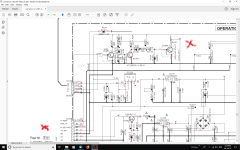
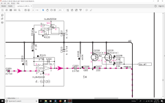
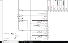
No luck finding a backup cap for the CPU but I tracked the subwoofer signal to just before the S/W RCA outlet on the + side of C293 in the middle of the first diagram. It looks to me like those transistors are muting the signal, can I just cut the muting track? Could it be that simple?
Attachments
Last edited:
you could cut the muting track, or remove the transistors, of course u might get nasty pops/thumps on input changing through the sub woofer
Its an end by not the right means🙂
Its an end by not the right means🙂
No luck finding a backup cap for the CPU but I tracked the subwoofer signal to just before the S/W RCA outlet on the + side of C293 in the middle of the first diagram. It looks to me like those transistors are muting the signal, can I just cut the muting track? Could it be that simple?
I'm confused, is this something that used to, or is supposed to work?
If so, I have seen damaged muting transistors before.
No luck finding a backup cap for the CPU but I tracked the subwoofer signal to just before the S/W RCA outlet on the + side of C293 in the middle of the first diagram. It looks to me like those transistors are muting the signal, can I just cut the muting track? Could it be that simple?
Not all product has such a cap but its always worth a look. It would probably be around the main CPU.
Before condemning the unit as genuinely faulty and modifying it, have you the correct remote/ instruction manual and are 100% sure everything is set correctly.
I'm confused, is this something that used to, or is supposed to work?
If so, I have seen damaged muting transistors before.
The unit used to work until I moved house but it wasn't dropped or handled roughly. I've checked the muting transistors and they are working OK with a DMM diode test.
Not all product has such a cap but its always worth a look. It would probably be around the main CPU.
Before condemning the unit as genuinely faulty and modifying it, have you the correct remote/ instruction manual and are 100% sure everything is set correctly.
I have the user manual and the service manual. I have set all the settings to their defaults, they've been done it at least three times and am 99% sure that the settings are correct. The manual says if the internal CPU is hung up, unplug the receiver from the wall, wait 30 seconds and retry. I've tried that a few times without luck and I know all the transistors are reading OK. I bought the Yammy new on sale for $225, a new Digital board is going to cost $220 so it looks like it will have to be a mute track chop because there is nowhere else to go from here, that's if I can, in fact, do that without stuffing something else up? 😀
Last edited:
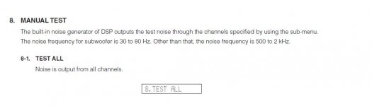
Might be worth trying the self test routine to see it output noise on the SW channel. No idea how the sub menus look but it implies you have to make sure the appropriate channels are already enabled.
All the channels are enabled, they come up on the display when I switch from one to the other. I can cut out the surrounds, center speaker, subwoofer, etc..The S/W is on. I've done the Self-test tones, it works on all the channels but the S/W. It's on the display like all the others it's just not putting out the sound. I've been right through all the self-diagnostics and submenus to try and find whats wrong with no luck? I've done it a few times but will do it again VERY carefully and get back with the result. I was thinking it may be a cold solder joint on a pull-down resistor for the S/W mute but where would that resistor be? I tried to copy and paste the CPU R5F364AMNFB Datasheet but its 88 pages so it must be too big.
All you could do would be to trace and measure the mute line from the chip to the transistors. Make sure that nothing odd is happening.
All you could do would be to trace and measure the mute line from the chip to the transistors. Make sure that nothing odd is happening.
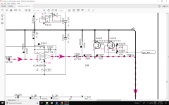
The mute signal goes from pin 80 on the CPU to Q2205 on the left in the first diagram, its supposed to have -11.7v on the collector going by the service manual but it only has 3.4v. This carries directly on to those other two muting transistors Q208 and Q209. All transistors test OK. The datasheet for the CPU says the mute port doesn't use pull up resistors, it uses a direction register? There are only a few resistors and caps along with the transistors that I've tested and they are all OK. I used a 10X jewelers loop to check the tracks and solder joints and reflowed a few bogie looking joints. I haven't done the self-diagnostics tests yet, its a real headache to understand because its written for Yamaha techs but I will do it again unless I can just cut the mute track with no major problems?
Attachments
Last edited:
The circuit should mute when pin 80 is either floating or actively pulled to the 3.3 volt rail. That will turn off Q2205 and allow the collector to assume the negative voltage needed to unmute. I can't see how it is pulled to -11 volts though.
If you short out B to E on Q2205 it should unmute I would have thought.
If you short out B to E on Q2205 it should unmute I would have thought.
The circuit should mute when pin 80 is either floating or actively pulled to the 3.3 volt rail. That will turn off Q2205 and allow the collector to assume the negative voltage needed to unmute. I can't see how it is pulled to -11 volts though.
If you short out B to E on Q2205 it should unmute I would have thought.
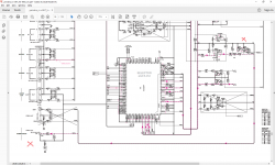
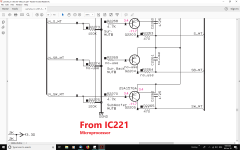
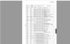
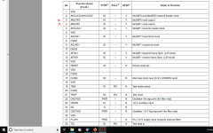
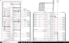
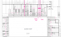
Nothing happened when I shorted the base of Q2205 to its emitter but when I muted the receiver the voltage on Q2205 base went from 3.270v (unmuted) to 2.600v (muted) I found two muting functions on IC241 Audio Processor going to flash memory. I lost track of it then? Diagrams 3 and 5 are of IC241 Audio Processor and 4 is the Flash memory. Maybe you can make sense of this Mooly?😀
Attachments
Last edited:
The change in voltage on Q2205 sounds correct to me. When muted, the uP pulls the base low and that is what you are seeing. In that state the collector should go high and be equal to the emitter voltage.
When unmuted the base should be high (high means equal to the emitter voltage). That turns the transistor off.
When the base is high, Q2205 should be off (effectively out of circuit) and so the collector voltage (which goes to the base of the mute transistors) should assume the -11v needed to unmute the audio.
I can not see how the -11 is derived. Normally there would be a collector load resistor for Q2205 that would be taken to a negative 11v rail but there is nothing.
The same arrangement is shown for all other muting transistors in the unit. Do you see those swing to -11v when activated.
- Status
- Not open for further replies.
- Home
- Amplifiers
- Solid State
- Yamaha 5.1 Receiver CPU.