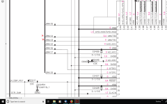
Yes, The other muting transistors swing to -11.7v when unmuted. I found two muting channels on the Audio DSP chip that goes to one of two flash memories. Both channels have a resistor at the flash memory In/Out pins if that means anything?
Attachments
Last edited:
I can't really see anything related around there tbh. I spent quite a long time looking at the full circuit yesterday and I'm baffled how the -11 volts is derived. Also you say you can see the base voltage change which indicates the mute on/off logic signal is OK.
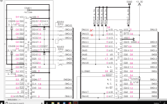
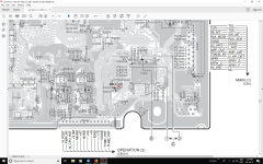
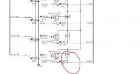
There is a 1uF cap next to Q2205 on the diagram. Is that OK and not leaky ?
There is a 1uF cap next to Q2205 on the diagram. Is that OK and not leaky ?
I can't really see anything related around there tbh. I spent quite a long time looking at the full circuit yesterday and I'm baffled how the -11 volts is derived. Also you say you can see the base voltage change which indicates the mute on/off logic signal is OK.
There is a 1uF cap next to Q2205 on the diagram. Is that OK and not leaky ?
I've been looking at the schematic for months now trying to work it out. It's a real mystery even a Yamaha tech couldn't help me with the -11.7v source? I will replace that electro cap and get back with the result.
What I would do if you don't find anything is to work back from a mute transistor that does work. See where the base goes, and what goes to the base. Try and find the source of the -11v bias voltage. Normally it would just be a resistor to the -12 rail.
Also, the muting transistor are a unique type and designed to withstand the -11 volts reverse bias across B-E.
Also, the muting transistor are a unique type and designed to withstand the -11 volts reverse bias across B-E.
The only electro cap near the CPU I see is a 33uf, 16v. Is this the one I should be wary of? I'm changing it anyway just in case. Oh, I just realized you said Q2205 transistor, so that's an SMD cap.
Attachments
Last edited:
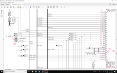
This one. If it was leaky it would keep the mute line high.
Also check for continuity from this transistor all the way back to the mute transistors. It might also be worth trying as a test to add a 47k or 100k from the collector of this transistor to the -12 volt rail and see if that fixes the issue.
Also check for continuity from this transistor all the way back to the mute transistors. It might also be worth trying as a test to add a 47k or 100k from the collector of this transistor to the -12 volt rail and see if that fixes the issue.
Attachments
On the face of it yes but as always check it out of circuit. If it reads OK when isolated then recheck and see if the short is still present with the cap removed. If it is then you need to investigate further to see what is causing it.
On the face of it yes but as always check it out of circuit. If it reads OK when isolated then recheck and see if the short is still present with the cap removed. If it is then you need to investigate further to see what is causing it.
It reads 0.9 ohms out of circuit. So that's more than likely the problem then?😀 There is 698k ohms across the gap one way and 0.00ohms the other way? I hope that's OK?
Last edited:
If it reads anything out of circuit then its faulty. All small non polarised caps should read infinity (open circuit) on a resistance test.
Just seeing that you mention 0.00 ohms across the gap 'one way'. That sounds odd but lets stick with the cap for now (you are sure you have actually got the cap and not some zero ohm link that looks like a cap 😉)
If it reads anything out of circuit then its faulty. All small non polarised caps should read infinity (open circuit) on a resistance test.
Thanks for sorting this out for me Mooly, I've learned a lot from this! When I saw your name in reply to my post I thought I had won the lottery because you are the only person I've come across who " always" solves things no matter how hard they seem to be? I've been trying to fix this receiver for months so thanks again Mooly, I really appreciate it.😀
Yes, I'm sure its the right cap. When I said I measured across the gap I meant the gap where the capacitor was in case there is any confusion? It reads 468 Mohms with the black probe on the Q2205 base and red probe on the far side of the gap. And 698Mohms the other way round.Just seeing that you mention 0.00 ohms across the gap 'one way'. That sounds odd but lets stick with the cap for now (you are sure you have actually got the cap and not some zero ohm link that looks like a cap 😉)
Last edited:
I will get another 1uf SMD cap tomorrow when the shop opens and solder it in. I'm sure the receiver is going to work now.Yay!!! Should I still do those tests from before like a 100ohm resistor to the negative 12v rail to the Q2205 collector? Because I have to install the board and take it out again to solder the new cap in, then re-install it again
Last edited:
Thanks for sorting this out for me Mooly, I've learned a lot from this! When I saw your name in reply to my post I thought I had won the lottery because you are the only person I've come across who " always" solves things no matter how hard they seem to be? I've been trying to fix this receiver for months so thanks again Mooly, I really appreciate it.😀
Thanks for the kind words 🙂 Lets hope we get a result on this one.
You can just try it without the cap and see if the -11 comes up.
It's getting late here in Western Australia, I was up all last night trying to figure this receiver out so I had better get some sleep first. I have to re-install the digital board to try shorting the collector to the negative 12 volts rail. so I will solder the SMD, 1uf, 25v, bipolar cap in tomorrow, install the board and see how things go and post back then. Thanks again Mooly!
Don't short the collector to any rail... I never said that 🙂
Post #26. Use a 47k or 100k resistor to the negative rail.
Post #26. Use a 47k or 100k resistor to the negative rail.
I don't quite understand your complaint.."will not switch to both front small speakers in the set-up to allow the sub-woofer to work?"
Do you mean if set to large front speakers u get no sub-woofer
and if you change to small front speakers u get sub-woofer operation?
That's the way Audyssey works. The large/small choice has nothing to do with speaker size or how good the bass is from those speakers.
Thanks for the advice but I already knew that.That's the way Audyssey works. The large/small choice has nothing to do with speaker size or how good the bass is from those speakers.
No luck getting a 1uf 25v SMD cap at the local electronics shop so I'm going to have to order it in. I've been trying to take them off some digital boards I have laying around but they tend to break very easily and when I do get a good one its the wrong value? If I short the collector of Q2205 via a 100k ohm resistor to the negative rail does it have to stay connected to the negative 12v rail to keep the transistor on or is it enough to turn the transistor on just by shorting it? I'm guessing it stays connected but I thought I had better make sure?
Last edited:
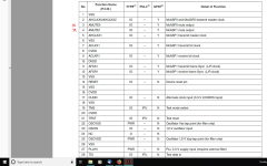
- Status
- Not open for further replies.
- Home
- Amplifiers
- Solid State
- Yamaha 5.1 Receiver CPU.