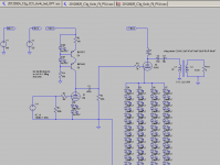
what does two secondaries mean ?
See attached picture. One can connect primaries and secondaries in series or parallel.
Attachments
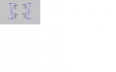
OPT
The xformer is definitely an OPT - 10W does not imply an IT, does it? I have used it before with 6C4C SE - it is air gapped one.
I changed cap connection as you suggested - the same response.
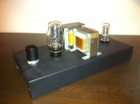
So it is time to make it real.
The xformer is definitely an OPT - 10W does not imply an IT, does it? I have used it before with 6C4C SE - it is air gapped one.
I changed cap connection as you suggested - the same response.
So it is time to make it real.
Last edited:
See e.g. this amp AFA parafeedcap (value) is concerned:
MagneQuest Transformers: DIY Schematics w/ MagneQuest Iron
MagneQuest Transformers: DIY Schematics w/ MagneQuest Iron
See e.g. this amp AFA parafeedcap (value) is concerned:
I suppose the cap is to block DC, thus its cut frequency depends on actual impedance
I suppose the cap is to block DC, thus its cut frequency depends on actual impedance
More on math regarding parafeed, read here: DHTsound
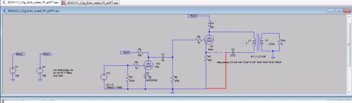
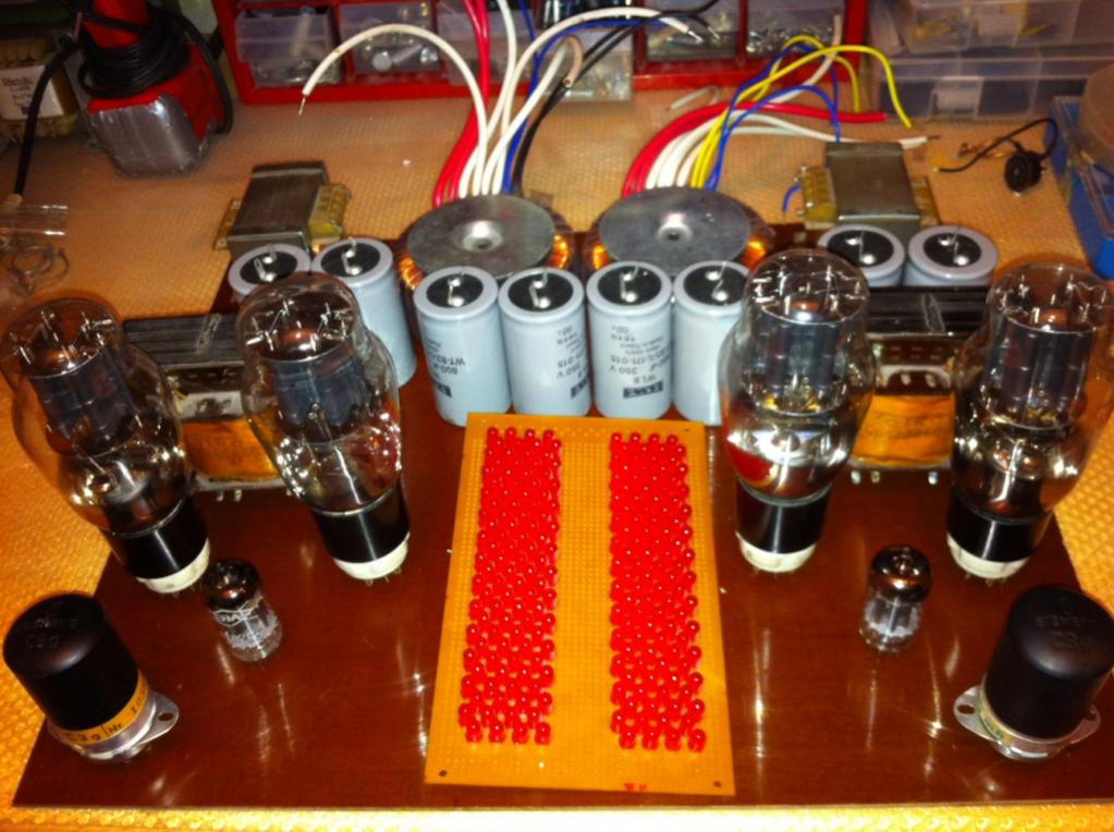
I think I reached the optimal schematic. So I start building a prototype.
First approach of a look below
First approach of a look below
Attachments
Last edited:
There is a mistake in supply voltages labels - Eav1 should be 220V and Eav2 should be 360V
Nope, wrong again. Correct values are:
Eav1 (c3g) = Ua triode connected + Ia*Ra = 200V + 15k*13mA = 395V, Uf LED voltage disregarded
Eav2 = Ua +Ia*Rl+ nUf =250V + 62mA*270ohm + 45V = 311,74V -> 310V
Last edited:
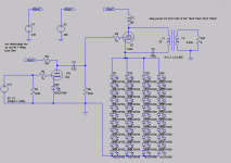
Is that high value for R3 necessary? Did the C3G suffer from oscillation?
Is there no noise issue on the 6C4C cathode with all those LEDs?
Is there no noise issue on the 6C4C cathode with all those LEDs?
Is that high value for R3 necessary? Did the C3G suffer from oscillation?
Is there no noise issue on the 6C4C cathode with all those LEDs?
Soldering is ahead of me. That is also my first experience with C3g - so your question is to be answered.
As for LED - I replaced RC cathode bias with LEDs and there was a huge improvement. I did not measure noise though.
Link to build thread of filament regulator for 6C4C
http://www.diyaudio.com/forums/powe...tracking-pre-regulator-current-regulator.html
http://www.diyaudio.com/forums/powe...tracking-pre-regulator-current-regulator.html

I will attach a pic when I fire them.Only 112 per channel 🙂 See attached pic from other thread.
Last edited:
just one tad bigger pictures, please
much too small to see anything
hey, btw, thanks to you(partly) I just now realized why voltage drop over the plate resistor should be calculated and added to supply voltage nice to know 😀
much too small to see anything
hey, btw, thanks to you(partly) I just now realized why voltage drop over the plate resistor should be calculated and added to supply voltage
nice to know 😀Original post with bigger pictures.just one tad bigger pictures, please
much too small to see anything
http://www.diyaudio.com/forums/tubes-valves/201402-12w-push-pull-w-6c4c-3.html#post2814678
Glad I could help 🙂hey, btw, thanks to you(partly) I just now realized why voltage drop over the plate resistor should be calculated and added to supply voltage
Recent schematic of the amp. Now assembly.
why don't you use fixed bias for power stage ? it is simple and easy to adjust the operation point.
many people here gave up the LED bias....
I am rebuilding the existing amp with LED bias, yet improving / experimenting with some elements i.e. filament power supply and driver stage. I decided to leave output stage bias as is. If I went to fixed bias I would have to change at least mains transformer, add another regulator. And then I would end up with another enclosure, and that would be new amp. I have 2 more projects on the table: SET w/300b and PP w/6C4C. So perhaps then.
As for LED - I replaced RC cathode bias with LEDs and there was a huge improvement. I did not measure noise though.
It's very low. Figure roughly 0.6-0.7nV/rt Hz per LED and the series string adds as power (not voltage).
- Status
- Not open for further replies.
- Home
- Amplifiers
- Tubes / Valves
- yagoolar's tube amp projects