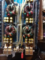
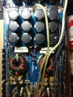
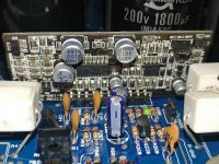
I'm currently working on an XXV Sampson, the power supply section comes on and relays click and I get a green status light. When i probe the FDA 24N40F output FETs, Q19-Q16R and Q11-Q13R are shorted, the same FETs on opposite sides of the board which is too coincidental so I get the feeling the output driver board could have an issue.
Mr. Perry Babin sent me a schematic of a similar board and reading it without any electronics repair training is proving to be a tough task but I'm slowly researching the components but I could really use some assistance with this if someone could lend some.
Also, if I'm not mistaken the FDA 24N40F wasn't the output FETs on the board before it was sent for repairs this last time. Is this component a proper FET for this amplifier?
As always I'm very grateful for any help I can get. I will try to post the best pics my phone can take and if there are any more needed I'm happy to take more. Thanks again
Last edited:
To upload photos click the following:
Go Advanced
Manage Attachments
Browse
Upload
Repeat as necessary
Preview post to see how the post will look.
Click Submit Reply to send it to the forum.
Go Advanced
Manage Attachments
Browse
Upload
Repeat as necessary
Preview post to see how the post will look.
Click Submit Reply to send it to the forum.
wanted to resize pics and got this error:
The administrator has specified that you can only edit messages for 30 minutes after you have posted. This limit has expired, so you must contact the administrator to make alterations on your message.
should i delete and re-do post??
The administrator has specified that you can only edit messages for 30 minutes after you have posted. This limit has expired, so you must contact the administrator to make alterations on your message.
should i delete and re-do post??
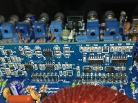
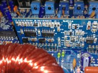
last pic shows FETs that are testing as shorted
Attachments
-
 20210217_150627.jpg468.3 KB · Views: 247
 -
 20210217_150618.jpg509.8 KB · Views: 247
 -
 20210217_150606.jpg548.5 KB · Views: 239
 -
 20210217_150642.jpg452.4 KB · Views: 232
 -
 20210222_140713.jpg175.5 KB · Views: 246
 -
 20210222_140723.jpg434.4 KB · Views: 171
 -
 20210222_140658.jpg443.9 KB · Views: 186
 -
 20210222_143051_LI.jpg568.2 KB · Views: 212
The 24N40F has been used a long time. Someone else should post if they know something better.
Do you have ANY experience repairing amps?
When any FETs fail, it can damage their driver IC which can drive voltage back into the 12v regulator, destroying other IC and possibly causing other FETs to fail.
With shorted FETs, it's odd that the power supply will power up.
What's the rail voltage in the amp?
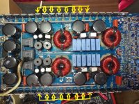
i removed the FMU36S and FMU36R rectifiers so that i could troubleshoot the input and output sections separately and isolate the issue.
I have very little experience in electronics repair but once I get a few issues with my house taken care of I intend on taking classes at a local college to learn more to better understand it. For now I'm mostly depending on the Amplifier Repair Basics section on BCAE, YouTube videos by BareVids, and now this forum. I'm waiting for a hard drive with Windows 7 installed to arrive for a seperate pc I have so that I can purchase the Amplifier Repair Tutorial on BCAE.
I have very little experience in electronics repair but once I get a few issues with my house taken care of I intend on taking classes at a local college to learn more to better understand it. For now I'm mostly depending on the Amplifier Repair Basics section on BCAE, YouTube videos by BareVids, and now this forum. I'm waiting for a hard drive with Windows 7 installed to arrive for a seperate pc I have so that I can purchase the Amplifier Repair Tutorial on BCAE.
Last edited:
Is it possible to check rail voltage with the Rectifiers removed? Or will i have to solder them back on?
thanks for the reply, even though it's not what i was hoping for, it took 5-6 hours to get them out. I didn't want to pull out any via's or mess up solder pads. And once that is done then i power it up, negative dmm lead on amp ground, and positive lead to the rectifiers?
What is it about the rail voltage do you want to know?
Please (and this applies to anyone who needs repair help) use your sig line to list all equipment you have, editing it as equipment changes. Include the model numbers.
Top of page, menu USER CP >> EDIT SIGNATURE
Oscilloscope (yes or no)
Multimeter(s)
Type of signal source (grounded RCA shields preferred).
Soldering iron
Desoldering pump
Power supply
2 ohm current limiting resistor (hollow cylindrical ceramic 100w preferred)
I just wanted to check to see if there was any rail voltage, just to ensure the power supply section was good to go! Don't have much equipment to speak of but i'll put what i have in my sig
Without the rectifiers, you can measure the DC voltage on the gates of the PS FETs to see if they FETs are being driven. That can be done with a multimeter set to DC volts.
With a scope, you can look at the input to the rectifiers.
If you're concerned about the vias, You could connect the rectifier legs to the board with wire jumpers. It's easier to desolder the single wires than to pull the rectifiers.
With a scope, you can look at the input to the rectifiers.
If you're concerned about the vias, You could connect the rectifier legs to the board with wire jumpers. It's easier to desolder the single wires than to pull the rectifiers.
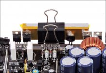
i might have to give that a try. Also, is it ok to attach 1"x1/4" flat bar to the heatsink side of the fets to avoid having to put the board back into the heatsink just to end up removing it again? There will be thermal paste on it also
since my last post I have removed all output FETs and re-installed rail transistors. I would like to fix some through hole locations where the Via's have been pulled out/removed. Where would be a good place to find some?? Thanks guys for the continued help
I tried the via replacement and never found them to be better than soldering the lead on both sides or using a wire to restore the connection.
- Home
- General Interest
- Car Audio
- XXV Sampson power up issues