I should be able to find more powerful power supply. I understand your comment about using higher rating especially that my original acted as a fuse and saved some other components.
I worked with 4 EEs that are now at JL audio. I will try to find more powerful power supply and report back. Though afraid of burning more stuff especially now knowing that your x603 is happy with 3a.
I worked with 4 EEs that are now at JL audio. I will try to find more powerful power supply and report back. Though afraid of burning more stuff especially now knowing that your x603 is happy with 3a.
To protect the FETs, test the amp initially with the FETs clamped tightly to their heatsinks and a current limiter (either a resistor, when necessary or a 15 amp fuse when a resistor will cause a problem).
To protect the FETs, test the amp initially with the FETs clamped tightly to their heatsinks and a current limiter (either a resistor, when necessary or a 15 amp fuse when a resistor will cause a problem).
Perry,
Are you suggesting to use 15 amp fuse in line with 12V? I was going to use benchtop power supply that can deliver 5A or 8A. I have tried 3A capable benchtop supply but it was switching to constant current mode with voltage sagging to 8.5V or so.
I will list provide power supply make and model once I get back to the office (hopefully this weekend). What I don't know is how far I should be pushing with current limiter.
A current limiter is used for initial testing. The series resistor is used for very low level testing when the condition of the amp is unknown. A fuse would be a limiter for higher power testing or when there is no current limiting.
Too many people use a battery (generally in the vehicle) with the large main power fuse. This offers very little protection. Using something like a 15 amp fuse can allow an amp to be driven harder than the resistor with little risk to the amp.
Too many people use a battery (generally in the vehicle) with the large main power fuse. This offers very little protection. Using something like a 15 amp fuse can allow an amp to be driven harder than the resistor with little risk to the amp.
I am back.
Took my amplifier to work. Found XFR 60-20 power supply that can deliver 60V up to 20A. Set the current limit to 4A. Connected the amp, powered on and boom. Spark and smoke... Link to the video.
Removed C160 once again and cleaned it. The two traces the spark is happening across measured ~50 Ohms. I measured it with C160 loaded and removed. It may look like the cap housing was shorting the traces but it is not the case. One of those 2 traces is -45V.
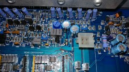
Can you guys check the resistance across the two test points I have circled in Red? The discharged occurred across them. Also knowing the resistance of various rails with respect to ground would be helpful (there are test points next to speaker output terminals).
I found R815 10Ohm resistor that looked like had severe overheating problem on -45V rail that measured 16Ohm (little 1206 guy). I had it replaced.
I have access to all kinds of lab equipment from oscilloscope, microscope to power supplies.
Took my amplifier to work. Found XFR 60-20 power supply that can deliver 60V up to 20A. Set the current limit to 4A. Connected the amp, powered on and boom. Spark and smoke... Link to the video.
Removed C160 once again and cleaned it. The two traces the spark is happening across measured ~50 Ohms. I measured it with C160 loaded and removed. It may look like the cap housing was shorting the traces but it is not the case. One of those 2 traces is -45V.
Can you guys check the resistance across the two test points I have circled in Red? The discharged occurred across them. Also knowing the resistance of various rails with respect to ground would be helpful (there are test points next to speaker output terminals).
I found R815 10Ohm resistor that looked like had severe overheating problem on -45V rail that measured 16Ohm (little 1206 guy). I had it replaced.
I have access to all kinds of lab equipment from oscilloscope, microscope to power supplies.
Attachments

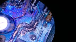
The board wasn't likely cleaned well enough. The darkened area under/near that capacitor is likely conductive and needs to be scraped out until you're down to clean fiberglass.
Thank you Perry. I suspect it was sparking in the area of the least resistance since I haven't cleaned it good enough. Thank you for the advice. The PCB burned out pretty bad there (formed a little crater). It would be fantastic if it is such a trivial repair...
If someone could ohm out the two test points I have provided it would be helpful. I will remove the cap and scrapped with the knife.
If someone could ohm out the two test points I have provided it would be helpful. I will remove the cap and scrapped with the knife.
You have to get back to 100% clean fiberglass. Anything that's even marginally discolored will likely continue to burn. In some repairs, the problem is so bad that the components in the area have to be wired point to point because there is none of the original board remaining.
I am back.
Can you guys check the resistance across the two test points I have circled in Red? The discharged occurred across them. Also knowing the resistance of various rails with respect to ground would be helpful (there are test points next to speaker output terminals).
See post 18, sentence 1.
You should stick with Perrys advice. The carbon crater is your #1 issue right now.
How do you adjust the DC offset on this amp? I think i got it up but getting 100mv of DC offset on some channels.
After you adjust the offset, monitor the offset with your meter and blow on the area where the drivers for that channel are located. What do you notice?
Ok found it. It is 500 ohm roots. I will share some photos later on. Thank you guys who helped get it up and going. I woldnt be able to accomplish this without your help.
The bias pots are 20k. I have found it by trial and error by monitoring power consumption on psu and DC offset. I don't know what bias is supposed to be set to though. I return it back but I would expect it drifted on all channels since the amp is quite old.
I also found another post for x603 that referred to 500 ohm rpots.
I also found another post for x603 that referred to 500 ohm rpots.
So here is my story about repairing this fellow.
1. I went back and started scrapping. I thought little more and I will have a hole in that PCB. Traces were up in the air by the time I was done. I ended up pouring super glue to fill in hole. 50 Ohms I was measuring across those two points turned into hundreds of kOhms or something like that. Can measure if anyone is interested.
2. Swapped 1W (or 2W) 12Ohm resistor with 0.5W 10 Ohm. Not sure what the original resistor is rated for but there is very small voltage drop across with no music playing. I may regret this later will see...
3. Connected to power supply and set current limit to 5A. Powered On, voltage is sagging to 9.5V while pulling 4.1A - 4.2A of current. No more sparks in the area I was working on previously. Checked voltage rails on the test point and there is no +45V.
4. Disconnected everything and brought back to soldering station. Used microscope to go around and clean any suspicious area with isopropyl alcohol and scrapping between traces in the area where water leaked.
5. Back to power supply, this time 12.5V and 4.1A of current load (DMM reading 11.9V at the amp terminals as I have used skinny wires).
6. Checking +45V at the test point, still missing it... Started ohmic out where -45V is going. It goes through 10Ohm resistor, then connected to another cap C159 and then further down the line. Apparently from the previous water leak (not severe) when I was cleaning the board I managed to damage the trace that goes to the test point (but nowhere else). I didn't bother fixing it (it would look uglier that it already is).
7. Went to recycle bin to find the speaker I can run test with. Found 3.5mm to RCAs cable in my cube.
8. Discovered that offset on the front channels was quite a bit off (130mV, -89mV) and rear channels were lower but still quite a bit off. Using trial and error method discovered that 500 Ohm rpots adjust the voltage offset. 20K rports adjust the bias. Later on found post on diyaudio that I needed 500 Ohm rpots (reference X603).
I didn't see Perry's post about: "After you adjust the offset, monitor the offset with your meter and blow on the area where the drivers for that channel are located. What do you notice?"
I let the amp run for some time (30 minutes) and adjusted the DC offset (<5mV). This those rpots are really sensitive. When I finished adjusting the last channel, went back to check and offset drifted to 20mV or so. Readjusted again, checked - they are in <11mV.
I guess the DC offset is temperature dependent. What is the proper technique to get it adjusted? This amp is mounted in the trunk (sits above X1001) and is used to drive my front speakers (bi-amping). In the summer it gets really hot and I wonder how much DC offset is going to drift.
Tested the amp, it is making noise on all channels through the mid-bass driver I pulled out of recycle bin.
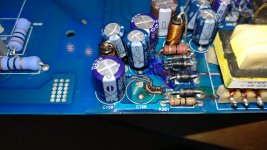
Attached are a few pictures. At the end I ended up using super glue to seal the exposed copper traces (after I used blue sharpie someone conviniently left at the rework station). 🙂
I took a video showing the temperature of the components after amp has been running for a while. Those power resistors run quite high. Link.
PS: Thanks again for your help Perry and Matthew. This forum rocks when it comes to helping someone (well car audio thread anyway). No help from JC though... 🙁


1. I went back and started scrapping. I thought little more and I will have a hole in that PCB. Traces were up in the air by the time I was done. I ended up pouring super glue to fill in hole. 50 Ohms I was measuring across those two points turned into hundreds of kOhms or something like that. Can measure if anyone is interested.
2. Swapped 1W (or 2W) 12Ohm resistor with 0.5W 10 Ohm. Not sure what the original resistor is rated for but there is very small voltage drop across with no music playing. I may regret this later will see...
3. Connected to power supply and set current limit to 5A. Powered On, voltage is sagging to 9.5V while pulling 4.1A - 4.2A of current. No more sparks in the area I was working on previously. Checked voltage rails on the test point and there is no +45V.
4. Disconnected everything and brought back to soldering station. Used microscope to go around and clean any suspicious area with isopropyl alcohol and scrapping between traces in the area where water leaked.
5. Back to power supply, this time 12.5V and 4.1A of current load (DMM reading 11.9V at the amp terminals as I have used skinny wires).
6. Checking +45V at the test point, still missing it... Started ohmic out where -45V is going. It goes through 10Ohm resistor, then connected to another cap C159 and then further down the line. Apparently from the previous water leak (not severe) when I was cleaning the board I managed to damage the trace that goes to the test point (but nowhere else). I didn't bother fixing it (it would look uglier that it already is).
7. Went to recycle bin to find the speaker I can run test with. Found 3.5mm to RCAs cable in my cube.
8. Discovered that offset on the front channels was quite a bit off (130mV, -89mV) and rear channels were lower but still quite a bit off. Using trial and error method discovered that 500 Ohm rpots adjust the voltage offset. 20K rports adjust the bias. Later on found post on diyaudio that I needed 500 Ohm rpots (reference X603).
I didn't see Perry's post about: "After you adjust the offset, monitor the offset with your meter and blow on the area where the drivers for that channel are located. What do you notice?"
I let the amp run for some time (30 minutes) and adjusted the DC offset (<5mV). This those rpots are really sensitive. When I finished adjusting the last channel, went back to check and offset drifted to 20mV or so. Readjusted again, checked - they are in <11mV.
I guess the DC offset is temperature dependent. What is the proper technique to get it adjusted? This amp is mounted in the trunk (sits above X1001) and is used to drive my front speakers (bi-amping). In the summer it gets really hot and I wonder how much DC offset is going to drift.
Tested the amp, it is making noise on all channels through the mid-bass driver I pulled out of recycle bin.
Attached are a few pictures. At the end I ended up using super glue to seal the exposed copper traces (after I used blue sharpie someone conviniently left at the rework station). 🙂
I took a video showing the temperature of the components after amp has been running for a while. Those power resistors run quite high. Link.
PS: Thanks again for your help Perry and Matthew. This forum rocks when it comes to helping someone (well car audio thread anyway). No help from JC though... 🙁
Last edited:
That's the problem with DC offset on these amps. Don't get too worried about it. It will not remain constant.
Using superglue or fast curing epoxy is a problem if you ever have to apply heat to either. If you have to fill a board, use the 24 hour curing JB Weld. For small areas, something like a drop of E6000 or GOOP works well.
For those two short traces, I'd likely have scraped away the solder mask back to solid board and overlaid a leg of a resistor over the length of the trace. Another option would have been to cut away the 'flying' part of the trace and jump them with a small gauge wire. Multi-strand (not the single-strand) ribbon cable works well. The wire could have been fixed in place with the adhesives mentioned above.
These suggestions are for future reference. There is no need to undo what you did.
When you scraped/dug the fiberglass out, did you take it back to where there was NO darkened fiberglass?
- Home
- General Interest
- Car Audio
- Xtant X604 repair help