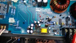
My trunk had a water leak and damaged that made its way in Xtant X604 amplifier.
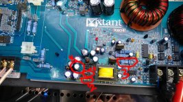
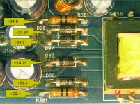
Does anyone know the part numbers for D96, D97, D98 and D99? If not can you please provide the voltage drop across them with DMM (both directions) and perhaps supply voltage while ON?
Also need to know the R361 value.
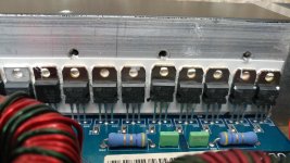
It appears the power supply has been damaged. C138 cracked opened and R361 is blown.
Does anyone know the part numbers for D96, D97, D98 and D99? If not can you please provide the voltage drop across them with DMM (both directions) and perhaps supply voltage while ON?
Also need to know the R361 value.
It appears the power supply has been damaged. C138 cracked opened and R361 is blown.
Attachments
Last edited:
To upload photos click the following:
Go Advanced
Manage Attachments
Browse
Upload
Repeat as necessary
Preview post to see how the post will look.
Click Submit Reply to send it to the forum.
Go Advanced
Manage Attachments
Browse
Upload
Repeat as necessary
Preview post to see how the post will look.
Click Submit Reply to send it to the forum.
You can still read the numbers on the diodes.Wipe them off and read the numbers. From the 4, you should be able to get a reliable number.
R361 and R381 are the same.
If the bottom of the board is as corroded, I'd use a fine wire brush to get back to clean solder (don't breathe the dust, use a vacuum to pull in the dust while brushing) before I'd try to desolder.
R361 and R381 are the same.
If the bottom of the board is as corroded, I'd use a fine wire brush to get back to clean solder (don't breathe the dust, use a vacuum to pull in the dust while brushing) before I'd try to desolder.
I found 1 shorted rectifier D99 diode. Lift one side on the other diodes as well.
With D99 removed I am still seeing 320 Ohms and raising up.
R381 is 10 Ohm resistor. Looks like 1/2W resistor.
I am going to order replacement parts. The diodes are Motorolla 1N4936.
Any advice on how to proceed further would be highly recommended. Does anyone has a circuit diagram or at least a portion of it?
Before you power up the amp, you need to clean up ALL of the corroded areas, check the components that had corrosion on them and redo their solder connections.
Some progress on the repair. Order replacement parts from mouser.
Swapped swollen capacitor, D99 diode, R361. I ended up ordering 1/2W and 1W resistors but by accident placed the order for 1Ohm 1W... I ended up using 12Ohm (11.6Ohm) resistor instead.
Put everything back together and connected to bench top power supply. The power supply has current limiting capabilities with Max current at 3A. I set the voltage around 13V. The power LED lights up, fan is spinning, I hear typical noise amp makes (no speakers connected). Though I did see a smoke after the initial power on and sparks by rectifier diodes. Checked the diodes no issue, but found capacitor (4) insulation damaged.
Grabbed thermal camera and identified components that are heating up:
1) 10 Ohm resistor R381. Measured voltage across resistor 1V. temperature gets to upper 30 deg C and slowly climbing up. For reference R361 had 1.2V drop (as I have mentioned i was using 12Ohm resistor instead of 10Ohm when I replaced it).
2) Diode D99. Same as R381 temperature gets to mid-upper 30C right away and slowly climbing up.
3) R362 0.2Ohm resistor (56C). Note that capacitor that sits right above has a bald head (insulation is missing).
Used test point and figured out +45V and -45V rails were down (perhaps not enough current to power on the amp section). I didn't take a note of all other voltage rails when I checked them. I did check all output transistors and didn't find any shorts. I thought I did but the parts needed up being rectifier resistors with 2 diodes connected together on one end.
Obviously I haven't fixed my problem with ad hock approach. The power supply was switching to constant current mode likely due to excessive current load (voltage was reading about 8.9V with current set to max 3A).
Any help would be appreciated.
Attachments
<small correction>
rectifier diodes, not resistors that are connected together inside the package (attached to heatsinks).
Rectifier diodes where I had the water damage generate: +27 and -27V rails.
rectifier diodes, not resistors that are connected together inside the package (attached to heatsinks).
Rectifier diodes where I had the water damage generate: +27 and -27V rails.

Thank you Perry. I will have to bring it back to work to continue to troubleshoot. Any idea how many amps the amp is pulling from power supply when idling?It's hard to know for certain if this supply (or any part of the amp) is working correctly when the amp is starving for current. These are the voltage from a working amplifier (from an X603).
The 603 pulls < 2a and I suspect the 604 is similar. You’re not powering this up and taking readings with all that corrosion still in the PS and audio section are you? That absolutely needs addressed.
I was just using the old picture to identify components on the board. I have cleaned the board. The only area I cannot completely clean is little transformer. It would require resoldering the part and I am likely burn the traces if I attempt that. I have used the brush to clean with isopropyl alcohol (90+%) as well as I could have.The 603 pulls < 2a and I suspect the 604 is similar. You’re not powering this up and taking readings with all that corrosion still in the PS and audio section are you? That absolutely needs addressed.
Unfortunately I don't get much time to spend on this device as I am dealing with family matters. Though would like to get to the bottom of it if possible.
Just lookin out for ya. I repaired an amplifier yesterday that someone powered up with electrolyte all over the board. It did a TON of damage.
I see one vented cap in the PS section that needs replaced and did you pull and clean under the others? Water and mineral deposits under electrolytics will wreak havok.
When you get back to this I have a 603 here if you or Perry need references. The 603 is essentially a 604 with a mono channel in place of the rear channels.
Just lookin out for ya. I repaired an amplifier yesterday that someone powered up with electrolyte all over the board. It did a TON of damage.
I see one vented cap in the PS section that needs replaced and did you pull and clean under the others? Water and mineral deposits under electrolytics will wreak havok.
When you get back to this I have a 603 here if you or Perry need references. The 603 is essentially a 604 with a mono channel in place of the rear channels.
Thank you Matthew.
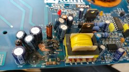
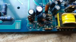
I took some pictures as I was going through. Unfortunately I had to use degreaser to clean the PCB as rubbing alcohol wasn't strong enough to remove debris. Though the traces got hot and the silkscreen washed out very easily. Attached a few pictures before and after as well as additional picture showing transistors and diodes where I thought I have found a short. I would have removed all components but soldering iron I have at home is not powerful enough and I end up damaging traces. This amp has 2 parallel wires (rework) soldered on the back that have almost no service loop and makes it very difficult to replace components. I applied capton tape to prevent wire insulation damage. Though when I am at work I can remove those wires to gather additional space (picture attached). You can see on the picture the area where power resistor got hot.
I would be interested in your resistance measurements across various rails on the test point with respect to ground. Also resistance at the test point Perry provided would be very helpful (rectifier diodes with respect to ground). I only have 1A capable power supply that is part of rework station at home so cannot really do much experiments without going to work and I don't even stay at home now days (working remotely), moved to my moms place as it is much closer to the hospital I have drive her to daily.
Since I had 1 diode and 2 resistors heating up it gives me the clue as to where to start looking. I already started deriving the schematic but had to stop due to lack of time... I feel it will be a long project.
Thank you for your help guys.
Attachments
The 'rework' wiring is factory. If you don't have a good soldering iron, I don't suggest trying to temporarily move it.
Which test points exactly? And which ground reference? Primary or secondary?
Which test points exactly? And which ground reference? Primary or secondary?
It definitely looks like factory wiring. I guess they ran out of real estate on the board for power rails or something.The 'rework' wiring is factory. If you don't have a good soldering iron, I don't suggest trying to temporarily move it.
Which test points exactly? And which ground reference? Primary or secondary?
I am interested in the secondary GND reference. Attached is the picture that shows various voltages that Perry shared with me. Resistance measurements would be helpful. I believe I have measured -27 and +27V on C160, C138 or those next to them. I had to replace one of those caps (actually swapped 2 for matching) as one was blown open. Those caps are rated 63V so Perry Voltages seem right and what I am measuring is likely due to some short... I didn't have a clear plan of attack. Brought the amp to work as I couldn't even solder diode back at home and then figured out I still have a problem and almost no time to really think anything through. Didn't want to keep the amp cooking too long either.
PS: I believe primary (chassis) and secondary are connected via 270 Ohm power resistor.
Attachments
If i'm understanding you correctly, you'd like resistance values between secondary ground and each of the points on Perrys voltage diagram. The trouble with that is the capacitors in circuit. Anything sub 100 ohm would be a red flag for investigation, if that helps.
I noticed in one of your posts that you were concerned about heat on these components. All of these parts should be good up to 85c (and some beyond that). None of the temperatures you posted raised any red flags.
c/o that post:
'1) 10 Ohm resistor R381. Measured voltage across resistor 1V. temperature gets to upper 30 deg C and slowly climbing up. For reference R361 had 1.2V drop (as I have mentioned i was using 12Ohm resistor instead of 10Ohm when I replaced it).'
These readings are fine.
'2) Diode D99. Same as R381 temperature gets to mid-upper 30C right away and slowly climbing up.'
Also fine.
'3) R362 0.2Ohm resistor (56C). Note that capacitor that sits right above has a bald head (insulation is missing).'
I'd call this fine, too. There will be differences between our equipment. But I get about 50c on this idle.
Lastly, I set my current limit to 3a and the amplifier was able to power up and stabilize. That does NOT mean yours should and will if there is a problem post-supply. Have you tested the outputs in the amplifier?
I think this satisfies your questions.
Hi Matthew,
Correct. Also by the speaker terminals there are test point for various rails along with GND. I recall that 45 and -45V were not active when I did a quick check. One of the lower voltage rails (I think 15V or so measured like ~8V). I didn't take any notes as I was not prepared for further troubleshooting and didn't even had pen/pencil around to take notes.
I only checked all output transistors and diodes for dead shorts that are mounted on the heatsink. I have compared the resistance across caps connected to diodes and found on one side it is lower. I think I was measuring 320 Ohms and raising up but after I cleaned all the gunk it went to 1.5K or so if I recall it correctly. I am surprised only one rectifier diode is getting hot. I have installed 2W resistor that is more beefed up than original (likely 1 W) and it is not heating up as much (better heat dissipation).
I have spotted a jumper for amp ON and OFF next to 12V power connectors. I wonder if amplifier circuit can be isolated by using this jumper.
The current across R381 is not excessive 1V drop across 1 0Ohm which is only 100mA. Basically it is only dissipating 0.1W.
PS: I am asking question and don't even have an amp in front of me. Sorry I cannot be more concrete.
Last edited:
'Correct. Also by the speaker terminals there are test point for various rails along with GND. I recall that 45 and -45V were not active when I did a quick check. One of the lower voltage rails (I think 15V or so measured like ~8V). I didn't take any notes as I was not prepared for further troubleshooting and didn't even had pen/pencil around to take notes.'
As Perry noted earlier, with the amount of sag on your power supply the main rails may never come up. You might be in a better place with at least 5a.
' I am surprised only one rectifier diode is getting hot. I have installed 2W resistor that is more beefed up than original (likely 1 W) and it is not heating up as much (better heat dissipation). '
Parts are not guaranteed to run at the same temps, especially when they supply different circuits. This is not a good way to search for problems. As for the original resistor (and somebody will correct me if i'm wrong) I believe Bruce Macmillan designed these amplifiers. Formerly of PPI and currently JL Audio. If the circuit needed a 2w resistor it would likely have one. Also, sometimes these components are spec'd to be sacrificial in the event of failure. So it's not always a good rule of thumb to go up in wattage. FYI.
'I have spotted a jumper for amp ON and OFF next to 12V power connectors. I wonder if amplifier circuit can be isolated by using this jumper.'
Just put this in the ON position and forget ya saw it.
Your measurements are ok so far. Perry is very good at helping people get to the bottom of things but you're gonna need to take a more 'test and report' approach. You're basically his hands and eyes. It would also help your cause to get the PS current up. Can you borrow a better PS? You could use a modified PC power supply with a large current limiting resistor or bulb.
- Home
- General Interest
- Car Audio
- Xtant X604 repair help