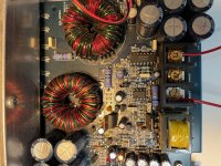
Hi, I am having trouble with this Xtant 403A amp as it won't power on. I also having another working one of this amp so I am able to compare. I did check all power supply diodes and mosfets and they seem to be good. No obvious burnt components.
When checking voltages I am not getting 12v on the power pins for SG3525 (pin 13) and UC3843 (pin 7). I trace these back to Q61 which appears to be the source for the power. My working unit shows 11.8v coming off the collector and 0v on the non working unit. In addition, when I trace voltage from the remote enable jumper it goes to R219 and D78 and I get 12v here but 0v and other side of each device. In the working amp there is ~6v on other side each device. D78 goes on to feed Q83 and Q71 which appear to control red power on led and feeds back to the base connection of Q61. Not sure what R219 is doing.
As I don't have a schematic hard to know what to look for, any help would be appreciated.
Thanks
Sean
Attachments
Yes, I think that is D78. When I check with diode tester I get ~600 ohm in one direction and really high ohm reversed direction on each amp zener. When I check the voltage with power on I get about 7V across working amp diode and 12v across non working amp diode. Does that probably mean zener not working as it is letting full 12v thru?
Are you sure that the A56 that reads 0v (0.000v?) from base to emitter isn't shorted?
Could you draw a diagram of this small section of circuit?
An alternative (not quite as safe), would be to bridge the transistor feeding pins 13 and 15 of the 3525 collector to emitter to force the amp to power up. With all FETs clamped and a 10-15 amp fuse in the B+ line, there shouldn't be much risk to the amp. If all channels work, you know the problem is in the control circuit. If you see a problem with one or more channels, that will lead the troubleshooting in a different direction.
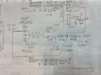
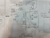
Here is what i traced out not sure what the other transistors are as they are small surface mount. The second image is what branches off from resistor R219 at top of first image. Not sure I completely traced that one out all the way.
I did double check A56 and it isn't shorted and measures resistance same as working amp one. I will fuse the supply and bridge A56 to see what happens.
Just to verify, should I bridge from the emitter to collector?
I did double check A56 and it isn't shorted and measures resistance same as working amp one. I will fuse the supply and bridge A56 to see what happens.
Just to verify, should I bridge from the emitter to collector?
Attachments
I should have been more clear, it is only pulling about 1.5 amp when I jump a56 which is about the same as the working amp.
The front L shows initially about -20mv dc but starts climbing to around -60mv as it warms up. Front R start about 20mv and climbs to 70mv. Passive L and R along with mono channel show .1 and are stable.
The front L shows initially about -20mv dc but starts climbing to around -60mv as it warms up. Front R start about 20mv and climbs to 70mv. Passive L and R along with mono channel show .1 and are stable.
The only thing I have that should be similar is nothing like what you posted.
Is the power supply staying powered up (producing rail voltage)?
Do you have ±15v on the power supply terminals of the op-amps?
Is there a j108 JFET in the audio section of each channel?
If so, what's the DC voltages across the gate and source terminals (black probe on the source)?
Is the power supply staying powered up (producing rail voltage)?
Do you have ±15v on the power supply terminals of the op-amps?
Is there a j108 JFET in the audio section of each channel?
If so, what's the DC voltages across the gate and source terminals (black probe on the source)?
The power supply is staying powered up although the last time it made a squealing should briefly and jumped up to pulling almost 6 or 7 amps before it settled into about 1.5 amp. It was jumping around quite a bit for about 15 seconds.
All the op-amps have about +13v on the power pins.
I can't seem to see any j108 JFets do they think they would be surface mount?
All the op-amps have about +13v on the power pins.
I can't seem to see any j108 JFets do they think they would be surface mount?
- Home
- General Interest
- Car Audio
- Xtant 403A not powering on