prints
Im getting my adapters delivered to me next week. excited.
Has any one printed an augerpro (somasonus.net) waveguide for the xt25? which one have you used (i will be printing the 6.5")?
Im getting my adapters delivered to me next week. excited.
Has any one printed an augerpro (somasonus.net) waveguide for the xt25? which one have you used (i will be printing the 6.5")?
XT25
xt 25 waveguide. It seems I was mistaken regarding using the augerpro 6.5". The only one that may fit the xt25 with no modification (dremeling) is the 5" ScanSpeak | somasonus. Issues with this waverguide: 1) its an older design ,has not got all the augerpro love for his choicest drivers. He has stated that he is not a fan of the xt25; 2) its a .75" depth, that does not suit the 6- 6.5" and bigger woofers (depth of the waveguide is designed to compensite for time delay in order to align acoustic centers). I found that the 6.5" woofer is the most interesting size when you are using tweeters with small waveguides, considering speaker baffle size and beaming of the woofer at desired crossover frequency.
The positives is that compared with the wg148, the most US availabe tweeter waveguide, augerpro 5" is bigger, at least on the x axis. Augerpro measures the waveguide on the payload, i.e. the convex/concave area connected to the throat. the screw mount flange is not counted. Example, a 5" augerpro waveguide is a 6" wide with 1/2 inch space for screws (6" 153 mm), while a visaton wg148r is 148mm including screws, so about 135 mm or 5 1/4" convex/concave). Likewise the 8" augerpro is 9" in total width.
I wanted to use ring radiators with waveguides, as they are supposed to work better that standard domes, and that is what drew me to the xt25 (soft, ring). But since waveguides are such a game changer for tweeters , i see the combo of the sb26 and the aguerpro 6.5" unbeateble for the price. I will keep experimenting with the xt25 as it is what I have on hand. We shoud start an active clone if the revel m106 with the sb26 and sb woofer. Count me in 🙂
I am printing the WG148R to xt25 adapter and the augerpro 5" to measuare and compare. Parts are printing on a crealty ender 3 now. Will uplodad pics when done.
Attachments
Last edited:
Post 665 details a way to improve the matching of the waeguide to the
driver . All text below is from mbrennwa
https://www.diyaudio.com/forums/multi-way/327657-source-tower-xl-67.html#post5613717
"The WG148 needs some machining to fit the Scan R2904 and D6600. The Blue Tack probably gives an air-tight seal, but you won't get a nice fit of the throat to the point where the dome / ring membrane is fixed to the tweeter assembly. I'd guess the rather poor response curves you got the from WG148 are the result of this. Also take a look at this, which allowed me to get a much smoother SPL response with the WG148."
"Well, almost... You need to modify the WG148 to fit the R2904 (or 6600 etc.).
First, take a look at an the unmodified WG148 here.
The thing is that even if you take off the face plate from the R2904 (or 6600 etc.), the throat of the waveguide still needs to "dive" in to the tweeter assembly. This means that the flange of the WG cannot be flat. You need to machine the waveguide in a similar way as described by Pida here (take a look at the attachment).
However, it's a bit more complicated with the R2904 or the 6600 etc. These tweeters require a slightly larger throat diameter of 39 or 39.5 mm instead of the original 38 mm of the WG148. To this end, I machined the WG148 by removing some material from its back flange until I got about 39.2 mm diameter. Then I cut a 3mm deep ring around the throat, similar as shown in Pidas drawing. Note that this means I actually cut away all the material of the flange back plate of the WG148 as shown on the first photo of my previous post. I only left the outer ring with the mounting holes/threads. The trick is to leave the right amount of material at the throat so that this part "dives" into the tweeter and seals the WG148 to the tweeter. I attached another photo showing the backside of the throat in more detail"
Last edited:
Member
Joined 2003
Nice!! Happy to see them be useful to others! 😀
Finally got them in hand, they're great. I would make 2 suggestions for perfection though. The cutouts for the terminals are a bit too small, widen the gap here a little to avoid having to trim some excess. I am using the original Vifa branded XT25TG30. I also notice that the backside is made for flat (tapered) screw heads, however the screws provided with the WG148 are pan head, so would be great to simply avoid the tapered hole here to have better fitment of a pan head screw.
Attachments
Last edited:
XT25 version
Thank you for the input.
Added a version for the XT25 to my Thingiverse project according to your feedback: Larger cutouts for the terminals, and removed the taper for fastening screws.
Thank you for the input.
Added a version for the XT25 to my Thingiverse project according to your feedback: Larger cutouts for the terminals, and removed the taper for fastening screws.
Member
Joined 2003
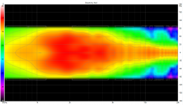
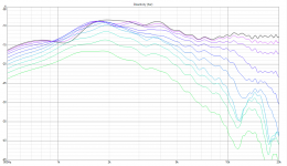
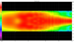
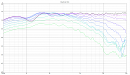
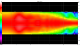
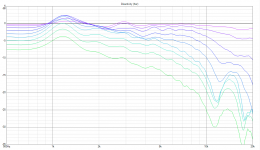
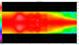
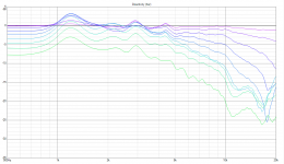
You've all probably seen these graphs before, but I had fun taking my own set of comparison measurements. Flush mounted on a large board, driver at same distance from baffle edges, so comparison should be apples to apples, with the exception that 2 different tweeters were used, but there is not much variance between them.
Overall I am seeing about 4dB of gain at 2kHz, and as you'd expect improvements to directivity and less diffraction effects from the baffle as well.
In order we have:
Factory face plate normalized line chart
Factory face place normalized polar map
Waveguide normalized line chart
Waveguide normalized polar map
Factory face plate raw response line chart
Factory face place raw response polar map
Waveguide raw response line chart
Waveguide raw response polar map
Attachments
-
 waveguide 102cm polarmap raw.png141.4 KB · Views: 256
 -
 waveguide 102cm polar line chart raw.png111.2 KB · Views: 271
 -
 factory 102cm polarmap raw.png129.8 KB · Views: 259
 -
 factory 102cm polar line chart raw.png97.1 KB · Views: 267
 -
 waveguide 102cm polarmap normalized.png129.7 KB · Views: 286
 -
 waveguide 102cm polar line chart normalized.png90.9 KB · Views: 408
 -
 factory 102cm polarmap normalized.png123.7 KB · Views: 410
 -
 factory 102cm polar line chart normalized.png86.7 KB · Views: 421
Crossover frequency
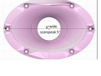
I am trying to use the waveguide with a 6 1/2 woofer, conde diameter 5 1/2, frame 7 1/2. The closest I can place the woofer and the waveguide together is about 7 1/2 " center to center or 184 mm. If I want to keep the spacing below one wavelength crossover , I have to choose about 1900Hz or a little bit lower (1900 Hz is 184 mm). I am not concerned about beaming as it happens around 34400/diameter (cm) which is about 2500 Hz for the woofer
Question: At what frequencies are you crossing?. Woofer is a mcm 55-5145
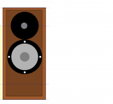
Attached is my preliminary design. 9" x 19.5" x 13.5" with a 3" port on the back at about 1 cuft tuned to 45Hz.
I am trying to use the waveguide with a 6 1/2 woofer, conde diameter 5 1/2, frame 7 1/2. The closest I can place the woofer and the waveguide together is about 7 1/2 " center to center or 184 mm. If I want to keep the spacing below one wavelength crossover , I have to choose about 1900Hz or a little bit lower (1900 Hz is 184 mm). I am not concerned about beaming as it happens around 34400/diameter (cm) which is about 2500 Hz for the woofer
Question: At what frequencies are you crossing?. Woofer is a mcm 55-5145
Attached is my preliminary design. 9" x 19.5" x 13.5" with a 3" port on the back at about 1 cuft tuned to 45Hz.
Attachments
Last edited:
Tks. planning to use vituixcad, little intimidated. Reading the manual and I am trying to have some metrics to build the box and then proceeded to make the measurements. For what I understand from VutuoxVad, you start by defining drivers, ports , size, then u proceeded to build, measurement, xover and if needed, new case.
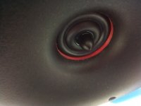
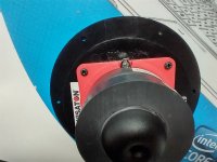
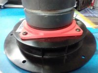
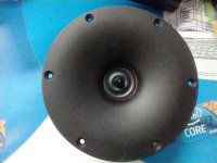
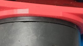
adapters installed
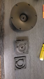
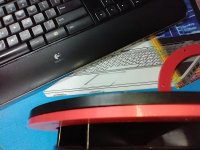
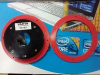
Finally I installed the adapters. They fit great but there were some play with the tweeter mounting screws. I had to use a small washer to keep it tight in one of the tweeter screw holes. Then I applied some clear silicone between the adapter and the waveguide. Some of the leftover silicone extruded out into the driver ( i was trying to seal and close the gap between the driver/adapter and the waveguide). The leftover silicone was used to seal the gap and the excess was removed with a small toothpick. The seal is perfect with no gap and the whole assembly feels very solid, like it came from the manufacturer as a single piece.
Printed on pla, second version of the adapter for the xt25. tks for a great part.
Attachments
Last edited:
Member
Joined 2003
I didn't use silicone to act as a gasket between the adapter and waveguide, but I did caulk around the outside edge to help prevent any leakage, both between the adapter and waveguide and on the driver side as well. Gave the waveguide surface a light sanding first with 320. It doesn't look pretty, but you'll never know once installed in a cabinet.
I did not sand (maybe I should have), but I used the silicone to buffer the imperfections of the part and to stop some minor movement of the driver. I have no idea if it leaks from the adapter into the waveguide, but I will caulk it. Augerpro also recommends on one of the posts to caulk/silicone the first magnet gap. ( have not done it yet).
Attachments
Member
Joined 2003
I'm not entirely sure that any caulking is strictly necessary, but it won't make it worse, so if it's intended to be a permanent installation then why not.
I made this ring so the wg 148r will have the same height as a woofer I am using in a 2 two way design. I am planning to 3d print a cover make the baffle so the drivers will be flash mounted.
Attachments
do i need to remove the face plate of the xt25 to use the adapter plate.XT25 version
Thank you for the input.
Added a version for the XT25 to my Thingiverse project according to your feedback: Larger cutouts for the terminals, and removed the taper for fastening screws.
. I can tell you that removing the faceplate is not a big deal and it is held by glue and three screws. If you use the 3d printed adapter, as I did, you have to remove it.
Member
Joined 2003
- Home
- Loudspeakers
- Multi-Way
- XT25 + Visaton WG 148 R with pictures