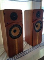
thanks Pete. excuse my lack of knowledge but what does FRD and ZMA stand for? Yes, I posted on AK about these. Are they the ones you are asking about?
That's them, very nice!
FRD is a file containing frequency response data typically in a format of freq, amplitude in dB, and phase in degrees.
ZMA is impedance in freq, ohms and phase.
They are typically comma delimited text files.
If you have these for your drivers mounted in that cabinet this is what you need to do a crossover design in any of the common simulators.
An alternative is to find these files, for your drivers, as measured by others, what are you drivers?
You might ask here or on the PE tech talk forum for the files.
We are kind of off topic here, why don't we take it to your thread on AK or start one here
on simulating/designing an XO for them.
Last edited:
Hi Bill,
been playing around with your neat simulator.
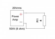
Something is bothering me though. The circuit
shows a simple 4 ohms resistor acting as a load
to the amplifier.
Vout= E rms= 20 V rms
R1= 4 ohms
---------------------
Current rms =I rms= E rms/R1
I rms=20/4= 5A rms
Power dissipated =Prms= E rms*I rms= 20*5= 100 W
Simulator shows dissipated power correctly, yet current rms
as current peak.
been playing around with your neat simulator.
Something is bothering me though. The circuit
shows a simple 4 ohms resistor acting as a load
to the amplifier.
Vout= E rms= 20 V rms
R1= 4 ohms
---------------------
Current rms =I rms= E rms/R1
I rms=20/4= 5A rms
Power dissipated =Prms= E rms*I rms= 20*5= 100 W
Simulator shows dissipated power correctly, yet current rms
as current peak.
Attachments

Hi zakman35,
A problem with user-supplied driver files being hosted in the Browser is that FRD files would have to be supplied in a standardized way so they can be used with other published files. Not the dots/commas issue, but drive levels and delay reference values.
I'll be publishing a simple "spec" for making "Standard FRD" files at some time in future addressing this. Basically, this will stipulate that the curves are to be measured at 2.83Vrms at 1m distance (or equivalent combination of drive voltage and distance to get the same levels). On an infinite baffle. And with a delay reference plane specified in the header (nominally and ideally, at 58usec behind the driver's mounting plane). All that to be stated in a header of the file like:
"| Standardized FRD file, measured by OmniMic "xxxxxx.omm" on 11/19/2013 by userID:
"| Equivalent to driven with 2.83V and measured at 1m
"| Acoustic origin is 58.23useconds behind the mounting plane.
"|
Sorry for the long reply!
Hi Bill, I'm planning to measure some tweeters with LAUD soon, I've done it many times
but I'm wondering if you have any tips to meet your 58.23 usec spec. You say that PE uses a reference driver, I wonder if I happen to have that driver if it would work. Hope your "simple spec" comes out soon.
...Simulator shows dissipated power correctly, yet current rms
as current peak.
Oops. Looks like you're right, I'll have to fix that. Thanks for the bug reprt.
Hi Bill, I'm planning to measure some tweeters with LAUD soon, I've done it many times
but I'm wondering if you have any tips to meet your 58.23 usec spec. You say that PE uses a reference driver, I wonder if I happen to have that driver if it would work. Hope your "simple spec" comes out soon.
Hi Pete,
With LAUD, you shouldn't have to do any delay derivations, you can measure true delay if you put the reference probe on the speaker's terminals. That will measure phase including actual delay from electrical input to microphone output voltage. You then have to correct the delay for the distance from the microphone tip to the mounting surface of the driver. There will be a slight additional delay from the microphone's bandwidth limit (maybe about 50usec) you should also remove. Sorry I can't give better detailed directions using LAUD lingo, but I haven't had a working LAUD system here for some years now.
Bill
Bill,
I used XSim last night. What a fantastic piece of software!
I'm not sure the X, Y, Z offsets are needed. You can use Holm to lock on to one driver and then measure other drivers relative to the first one without changing mic position. That should get you relative phase between drivers, which is really all we care about.
I was up and running pretty fast. Really love the flexibility and intuitive interface. Right click -> Tune... yeah baby!
I would also make a plug for the target curves. I may not stick with them, but it's nice to know what a 24 db/octave slope looks like. Of course, I can always get it through Holm or PCD.
Oops. Looks like you're right, I'll have to fix that. Thanks for the bug reprt.
I would really like to have the upper high frequency limit raised to 50 or 100K for
looking at XO networks. I have a 9 KHz notch with strange behavior around 20 to 22K
that is hard to see. Hmm, this has me wondering, what would the program do when the ZMA ends at 20K and you need to go beyond, estimate based on a curve fit?
Also, many metal dome tweeters have resonances often above 20K yet the program seems to be limited.
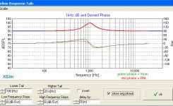
Has anyone tried the derived phase option in the driver tune window? I'm not sure if it is just my system but it does not seem to render correctly and I have trouble getting out of it. I found that if I tab through the data entry boxes and hit return, eventually I hit the one that closes the window.
I also do not think that I'm getting good phase from it, any tips for how to do this?
I tried some traced driver files without phase and the derived phase doesn't seem right.
I also do not think that I'm getting good phase from it, any tips for how to do this?
I tried some traced driver files without phase and the derived phase doesn't seem right.
Has anyone tried the derived phase option in the driver tune window? I'm not sure if it is just my system but it does not seem to render correctly and I have trouble getting out of it. I found that if I tab through the data entry boxes and hit return, eventually I hit the one that closes the window.
I also cannot get out of the derived phase pop up menu without crashing.
That menu really lacks the "Close" button.
Hello Bill, except xyz speaker position , I would propose the possibility to change the distance measurement , a very useful thing
Excellent software. Thank you very much.
If I may suggest a change - please add an option to specify D.F. of capacitors instead of only ESR. For electrolytics, this could make a significant difference.
I also noticed a small bug. in the "Group delay" window, the cursor position readings are wrong (only usec and doesn't correspond to graph).
Hello Bill, used Xsim some smoothing, it could be set optionally turn off ?
And also the thickness of the lines
And also the thickness of the lines
Hi Bill, been using XSim for a day or 2 now, and for someone with very limited knowledge/experience with crossovers, I've found it a great way of getting to grips with how things work. Great!!
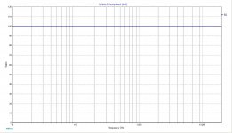
Just have one question (bear with me as I'm a total noob) what does the sys° line represent and 'ideally' what should it look like?
Some sims give me a reasonably constant level and some go off the bottom and back on at the top?
Thanks!!
Just have one question (bear with me as I'm a total noob) what does the sys° line represent and 'ideally' what should it look like?
Some sims give me a reasonably constant level and some go off the bottom and back on at the top?
Thanks!!
Is version 1.1.01 the latest version?
When trying to load a FDR file, I get a "file load error!" meassage .... anyone tried this?
I found some fdr files here:
https://app.box.com/s/qa3g6ukzxp6410dwmcrv
(from DIYAudio user "woolf-teeth")
no matter which one I try to use I get this message.
(the files look fine ... so I dont think this is the problem)
Thanks in advance, Baldin 🙂
Baldin,
The file load error message appears if the FRD files are not fully correct. Check the "layout" of the .frd files in a text editor .
Regards,
Eelco
The file load error message appears if the FRD files are not fully correct. Check the "layout" of the .frd files in a text editor .
Regards,
Eelco
- Home
- Design & Build
- Software Tools
- XSim free crossover designer