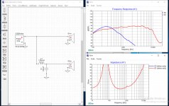
Simulated 3 filter versions with target curves BK/JBL/7dB and got 3 component value configurations. ABSOLUTELY GREAT! Ready for assembly,measuring and above all listening to compare ;-)
I did some thinking and I realized that the offset includes the angle, so for getting the offset on the baffle, I need to do some math. However, this still does not explain why with larger distance I get larger offset. If I am correct, it should be actually less because the angle is narrower.
Edit: It actually behaves as I expected🙂 I think I mixed up the numbers. Next time I will measure on the tweeter axis and do the math better. The good news is that the horn is confirmed too short and I can make a deeper one next time.
Edit: It actually behaves as I expected🙂 I think I mixed up the numbers. Next time I will measure on the tweeter axis and do the math better. The good news is that the horn is confirmed too short and I can make a deeper one next time.
Last edited:
Does anyone know if this is still available? I gust tried to do a download and it won't even take me to the page.
Does anyone know if this is still available? I gust tried to do a download and it won't even take me to the page.
I just clicked the link to XSim ( found in Bills signature ) and that link opened a download window waiting for me to download the XSim.exe file.
Therefore, the link works as expected.
Perhaps your computers security settings are preventing this download window from opening.
🙂
IS there any way of converting manufacturer's t/s parameters (like .txt) or those obtained by DATS2 program into usable files for this program?
Thanks in advance.
Thanks in advance.
XSim doesn't do anything with t/s parameters (those are for box design, not crossover design). You can use the ZMA exported impedance data for XSim's impedance curves of drivers being designed for, though.
Carl and woody, you can get great help here to use this magnificent software, however first there are a few things you need to do.
As I understand speaker crossover design you need to get your drivers in your enclosures and measure the individual driver frequency response and impedance. You also need to measure the combined frequency response of your drivers.
Once you have your zma and frd files the crossover magic can begin!
So for an open baffle I have to measure frd and zma with the drivers already placed in the baffle? Maybe is a stupid question but I never used this kind of software...
Correct. Applies to any speaker, not just dipoles. You measure the response of the drivers from a reference location on the baffle (or in the enclosure) they are used in / on.
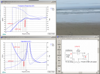
Nope, that's real. The inductor and capacitor form a series resonant circuit (narrow band impedance transformer), making the voltage at their connection higher than the power amp's voltage, so more power is applied to the speaker near the resonant frequency. The tradeoffs are (1) it makes the load impedance drop at the resonance and (2) it only works over a small frequency range and drops the level at most other frequencies.
There's a similar trick you can do with some woofers where you can feed them through a large series capacitor. The cap resonates with the inductive part of the woofer's impedance and pushes a boost into the response at resonance, similar to venting a box.

(There are some bugs in XSim 3D, but that's not one of them 🙂 )
There's a similar trick you can do with some woofers where you can feed them through a large series capacitor. The cap resonates with the inductive part of the woofer's impedance and pushes a boost into the response at resonance, similar to venting a box.
(There are some bugs in XSim 3D, but that's not one of them 🙂 )
Attachments
Last edited:
How do I simply input my driver parameters?
Not so straight forward as I can see so far.
Shouldn't need to be a programmer to use your software.
Sure hope I'm missing something.
Thank you,
The best Ron
Not so straight forward as I can see so far.
Shouldn't need to be a programmer to use your software.
Sure hope I'm missing something.
Thank you,
The best Ron
No...
This is not an enclosure simulation where you key in the driver's parameters and get a box.
This is for a crossover simulation, so you need the frequency response and the impedance of the drivers to correctly come up with an electrical passive filter between the two.
Either Google for more information, or, if this is too hard, go with a Full Range driver (no XO) or build a kit with XO components already calculated for you.
It's not rocket science, but you need to understand the concepts, at least.
How do I simply input my driver parameters?
Not so straight forward as I can see so far.
Shouldn't need to be a programmer to use your software.
Sure hope I'm missing something.
Thank you,
The best Ron
For sure some basic electronics knowledge is required to use this software. It is not for beginners. That being said do some online basic electronics courses and you can probably figure out how to use it. Read about crossover design and theory. Use a few simple crossover design packages to model basic first, second order crossovers to get a feel for what each type of component does. If you know all this my apologies.
But speaker driver parameters are not sufficient to characterize the drivers. You need frequency response curves and impedance curves saved in the correct formats. Easy if they are available online but hard if you have to create them.
This software took my crossovers to another level.
- Home
- Design & Build
- Software Tools
- XSim free crossover designer